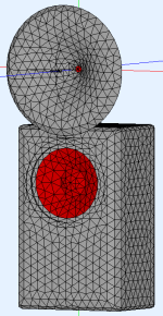
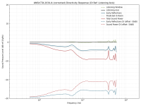
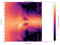
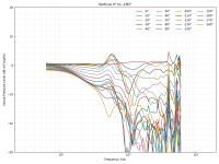
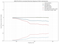
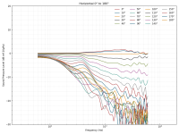
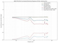
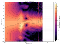
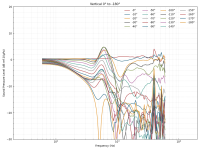
I tried a freestanding simulation with the same center-center spacing as before, which results in some overlap between the woofer and the edge of the waveguide. The waveguide profile is the same except for the added rollback:
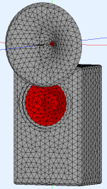
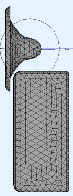
I disabled NUC for this since it resulted in garbage for the tweeter output, so ignore the weird spikes above ~4kHz. Needless to say, I succeeded in making the problem much worse 😉:
I'll try another sim with wider spacing to see if that improves things.


I disabled NUC for this since it resulted in garbage for the tweeter output, so ignore the weird spikes above ~4kHz. Needless to say, I succeeded in making the problem much worse 😉:


I'll try another sim with wider spacing to see if that improves things.
Can you show the woofer-only sim without the waveguide of the same enclosure that has the biggest baffle area below the woofer?
How does it look along a diagonal? Maybe the equal H/V weighting in the calculations is giving the vertical response too much weight. If it was this bad, we would regularly see in-room-response peaks of the woofer when measured around the listening spot (while flat on-axis). I don't think this is what happens - not so strongly. In the same way there would have to be a corresponding dip in the real measured raw on-axis response of the woofer, just due to the mere presence of a waveguide.
Anyway, great data.
Anyway, great data.
Last edited:
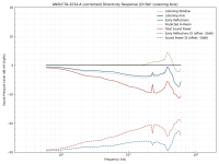
Forgot to turn NUC back on, so ignore the spike. This is using the same reference point as the narrower C-C example:Can you show the woofer-only sim without the waveguide of the same enclosure that has the biggest baffle area below the woofer?
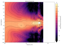
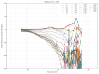
I can take a look. My poor 12-year-old laptop can only run these sims so fast though 🙂.How does it look along a diagonal?
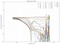
Here's the wider spacing one, computed only along the ±45° diagonal (ignore the plot titles):How does it look along a diagonal?
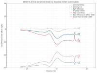
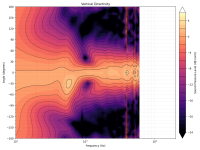
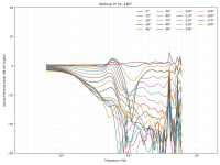
The crossover has a much greater effect on the computed sound power since the nulls are in both orbits. Here's the same data, but with a 5th-order butterworth crossover instead of LR6:
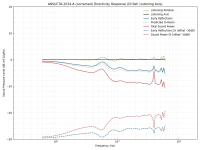
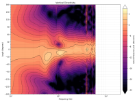
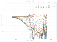
There is indeed. Here are the raw, non-normalized curves for the woofer from the narrower C-C sim (normal H/V orbits this time):there would have to be a corresponding dip in the real measured raw on-axis response of the woofer

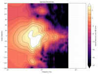
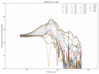
All I can say is that this is one of the strongest arguments I've seen for having a big horn covering the widest range possible. Or a good MEH 🙂
- Looking at the graphs, can we counteract the two effects (the wg interference + the crossover) with a careful design? They would "only" need to be located around the same frequency, I guess.
- Looking at the graphs, can we counteract the two effects (the wg interference + the crossover) with a careful design? They would "only" need to be located around the same frequency, I guess.
Last edited:
That would be one way to deal with it. Here's the wider C-C spacing sim with a 550Hz LR6 crossover (standard H/V orbits):Looking at the graphs, can we counteract the two effects (the wg interference + the crossover) with a careful design? They would "only" need to be located around the same frequency, I guess.
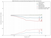
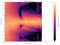
Edit: LR4 looks a touch smoother:
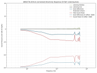
Last edited:
That's a lot better indeed.
This is good stuff! So, you have a flat DI from 600 Hz with how large devices? Is that a 12" woofer?
This is good stuff! So, you have a flat DI from 600 Hz with how large devices? Is that a 12" woofer?
Last edited:
Yes, it's a 12" woofer. The waveguide is just the same profile as in the speakers I built (with the waveguide integrated into the baffle), but with a rollback tacked on. Outer diameter is ~46cm.So, you have a flat DI from 600 Hz with how large devices? Is that a 12" woofer?
So what about the original enclosure with the baffle-mounted WG. If you were able to use the lower crossover point, wouldn't it be even more favourable?
Sure, but in terms of power response this is certainly a good thing to have. Better than a non-flat DI.
This is actually very good. Who would have thought about using those vertical nulls to an "advantage"...
550 Hz is not unreachable.
This is actually very good. Who would have thought about using those vertical nulls to an "advantage"...
550 Hz is not unreachable.
Last edited:
Hmm. Definitely, at the time of writing that post, I had the latest version of Bempp installed. Judging by the release dates, it was version 0.3.1. I can't tell you the versions of the other packages, but they were definitely the latest at that time.May I ask which version of bempp you used (bempp [C++], bempp-cl [python + opencl/numba] or bempp-rs [rust])?
I have started playing with bempp-cl which seems to the current version and it is not running efficiently for me. It does have periods running with a full set of threads but much of the time it is running single threaded. With your benchmark it is took about 50 seconds to assemble and 325 seconds to solve. In contrast a simple threaded "teaching" C BEM code took 7 seconds to assemble and 6 seconds to solve using a direct method. This is in line with your bempp results and what I was expecting to see for bempp.
Did you continue looking at bempp?
https://github.com/bempp/bempp-cl/releases
Hmm. Definitely, at the time of writing that post, I had the latest version of Bempp installed. Judging by the release dates, it was version 0.3.1. I can't tell you the versions of the other packages, but they were definitely the latest at that time.
Thanks. That is the bempp-cl version which I am trying to get working. May I ask how you installed your copy: a docker image, installing individual python packages or some other way? (I currently don't have space in my /var partition for another wretched container package).
It's encouraging that you have seen it running efficiently and so I guess my issues are with numba, opencl or whatever makes the package use compiled threaded code rather than python. Something I know nothing about, am not interested in but I guess I am going to have to learn.
PS Perhaps I should add that software currently runs and produces what looks like valid answers but just too slowly to be useable for frequency sweeps. I did come across some bugs I got round and much of what was in the original C++ version to make it a BEM toolkit is not in the current python version. Perhaps the intention is to put back in the rust version though the pros and cons of rust do not make it an appropriate choice of language for the task.
Last edited:
Forgive me for probably asking this again... what "mic" distance is the simulation done from and what "gate" is implied / used?Do note,
I suppose I'm asking what kind of real world setup (DUT, mic and e.g. REW) that would have to be present in order to expect a measuring result "equal" to the simulation.
//
To make sure we understood each other correctly: do I see the response only for the woofer in its second enclosure version (for the 'free-standing' waveguide), without the waveguide in place (neither firing nor reflecting)? If this is the case, I see my point proven that the extra energy is a result of a big reflective surface adjacent to the woofer. It's not (so much?) about its shape, but surface area. If this is the case, modifying the shape of the baffle enclosure (and not the waveguide) could probably solve the issue.
Another option if one does not want to create a bended/shape-shifted enclosure could be to work asymmetric slopes and x-over points. Maybe this can counter the extra energy due to reflections without the need to cross as low as 550 Hz. I had good simulation with BW18 + LR24 woofer/tweeter slopes where the woofer would usually cross higher than the tweeter if I remember correctly (or the other way round if I don’t). This lobe optimization is better suited for VCad work and extra simulation runs unnecessary.
Yeah depends on what one is looking from a system, multiple ways to address this stuff, kinda, depending what's more important the graphs or overall visual appeal, how easy it is build and measure and so on, a lot of stuff that affect eventual quality.
I've recently built big two way and cannot overestimate how important it is to get proper data and then spend time tweaking xo making sure the sound is good. I mean it took me quite a while to weed out issues with measurement setup, data processing and xo implementation, in general get sound workin', and my xo is around 800Hz, with DSP! Not sure how you guys do it with these big systems with home measurements and low xo points, and with passive parts.
My experience was that eventually it's quite big part of work to get the xo tuned properly. One could make it work by luck or by experience I guess, and possibly be fine in a ballpark because such speaker is already quite nice compared to any home hifi systems, even if the xo wasn't spot on. I urge to put good effort to get proper data and spend as much time tweaking as necessary, what ever it is that you are doing. Even to extent that the whole built is made so that the xo is high enough and the structures small enough it is possible to get good measured data in the circumstances one has. Some ideals like heavy box or nice polars don't mean that much if the system cannot be tuned to it's best. XO are easy in sims like vituixcad, but it's another question to get good data for it, and then to evaluate whether it was good or not.
Last edited:
The region around 300 - 1000 Hz can be tough and there's no simple cookbook, as there will hardly ever be really good acoustic data. One general "rule" is that the lower in frequency you are, the better sense it makes simply trying to get nice, balanced response around the listening position, including the room, certainly below 400 - 500 Hz. And that's not so difficult. If you make a flaw in the crossover, you'll see (and hear) it.
Last edited:
That's where a 3 way synergy horn with it phase tricks excel. Just sounds so together.The region around 300 - 1000 Hz can be tough and there's no simple cookbook
I'd like to explore a printable compression driver / mid driver waveguide mount, the front section for the 10 or 12" mid bass drivers could be trad wood.
Just don't have the expertise to do it printably - I'll go back to chopping wood😂
Last edited:
- Home
- Loudspeakers
- Multi-Way
- Acoustic Horn Design – The Easy Way (Ath4)
