Fantastic - these will look and sound awesome I'm sure. Could the full A620G2 body be included as STEP file in the package?
Last note on glue - the winner was 2 part epoxy. The sample chips I glued with Gorilla Glue seemed to stick well enough, but a little prying was able to split the glue line with no damage to the plastic, and the residual glue just peeled off like rubber. That's a fail in my book. CA was strong, but won't fill gaps. I tried some epoxy from the home store, and I can't get those pieces apart. I used the rest of the dual-syringe pack to glue up one ring of petals, and it seems sturdy. I'm not going to try to break it! I have some bigger bottles on the way to have enough to glue the other ring and the rings to the bases. Now to do the final fitting on the other set of petals. Should be making sounds by Monday.

For 2" throats I'm finishing a spherical-wave plug as a Gen2 adapter. The idea is to transform a flat wavefront into sherical, improving the HF directivity considerably.
This is the A620G2 with a regular 2" throat:
And this is a 2" throat with the shaping plug:
Last edited:
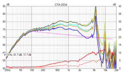
Polars 0-90/10° "measured" 0.5m from the mouth (just for reference 🙂)
(The above was at 2m with the throat as the origin, 0-180/5°.)

(The above was at 2m with the throat as the origin, 0-180/5°.)
Last edited:
This is the same 2" shaping plug (actually a "regular" Gen2 adapter) with the A460G2:


So, this is for the theoretical part...
So, this is for the theoretical part...
Will the phaseplug thingy scale? I do have a few sets of JBL 2490s laying around from my JBL 5674s and this could be fun to experiment with. Such a fun hobby!!
Just daydreaming of covering 400-8000 Hz with one horn with one compression driver. But soon finished with a synergized 520 horn so this is probably not going to happen.
Another random question:
The base piece of the A460 has a groove that appears to be sized for a 6mm x 70mm ID o-ring to seal the joint between the horn and the adapter. Are folks using an o-ring there? Is 70 durometer BUNA suitable? Or something else to seal the joint like a printed TPU ring? Or nothing at all?
I can't find anyone local that stocks metric o-rings (at least without an industrial account to get me in the door). I can order them but shipping costs much more than the parts. Still a lot cheaper than a spool of TPU I guess.
Thanks,
Bill
This is perhaps slightly off topic, but I thought it might be useful data of some relevance to this thread. About 5 years ago, I built a pair of two-way speakers with a large waveguide integrated into the front baffle (see this post for more info). The measured directivity performance is pretty good, but I did notice a disturbance in the woofer's vertical responses around 600Hz. I thought for some time that it might have been a measurement error, but I never got around to doing better measurements.
Recently, however, I decided to try simulating the complete loudspeaker as an alternative to real measurements. I didn't know how to do this when I did the original design, but I've acquired somewhat better Gmsh and ABEC3 skills in the last few years. Here are the original measured curves, normalized to the intended listening axis (18°):

Due to the short time window, the minimum valid frequency is ~400Hz. Simulation results, 60Hz-6kHz:

Taking into account the limited frequency resolution, the agreement is quite good. The distance also differs a bit—3m for the sim and probably about half that for the measurements (I don't recall the exact distance).
Measured and simulated horizontal contours:


Vertical contours:


I set up another sim with the waveguide completely absent and found that the vertical aberrations in the woofer's response went away. So, clearly the waveguide is to blame. I don't know what the audible impact might be (if any), but I'm wondering if a freestanding waveguide might cause less disturbance overall. Has anyone here simulated or measured the effect of a freestanding waveguide/horn on woofer directivity? I may try to simulate this myself at some point.
Recently, however, I decided to try simulating the complete loudspeaker as an alternative to real measurements. I didn't know how to do this when I did the original design, but I've acquired somewhat better Gmsh and ABEC3 skills in the last few years. Here are the original measured curves, normalized to the intended listening axis (18°):
Due to the short time window, the minimum valid frequency is ~400Hz. Simulation results, 60Hz-6kHz:
Taking into account the limited frequency resolution, the agreement is quite good. The distance also differs a bit—3m for the sim and probably about half that for the measurements (I don't recall the exact distance).
Measured and simulated horizontal contours:
Vertical contours:
I set up another sim with the waveguide completely absent and found that the vertical aberrations in the woofer's response went away. So, clearly the waveguide is to blame. I don't know what the audible impact might be (if any), but I'm wondering if a freestanding waveguide might cause less disturbance overall. Has anyone here simulated or measured the effect of a freestanding waveguide/horn on woofer directivity? I may try to simulate this myself at some point.
Did you leave the baffle above the woofer for the sim without the waveguide? My simulations always showed significant disturbances in the vertical results due to the baffle.I set up another sim with the waveguide completely absent and found that the vertical aberrations in the woofer's response went away.
Yes.Did you leave the baffle above the woofer for the sim without the waveguide?
Edit: Here's some simulated data for the woofer only with no waveguide:


The vertical directivity isn't perfect, but there's no strange peak in the sound power.
Last edited:
The eyes in the vertical pattern above and below the 0 point are unavoidable when there are two vertically spaced drivers in the speaker. This can be changed and blended in the crossover but it is very difficult to do that with an in phase symmetric LR4 if that is what was used. The woofer solo sim looks realistic and seems to have 7dB of DI around the 1000 to 1100Hz point, what seems a bit odd with some of the combined ones is that there seems to be a large DI difference between the woofer and waveguide which is where the bump dip is created.I set up another sim with the waveguide completely absent and found that the vertical aberrations in the woofer's response went away. So, clearly the waveguide is to blame.
You should be able to easily blend a 7dB woofer with 9dB waveguide, but in one image the woofer is at 4dB and the waveguide at 9dB and this does not look realistic for a large woofer to have such a low DI.
The nulls around the crossover frequency (1050Hz; LR6) are not what I was referring to. For clarity, here are the meshes with and without the waveguide:The eyes in the vertical pattern above and below the 0 point are unavoidable


And the corresponding directivity of the woofer:


Different driving groups may be observed separately. See theI'm confused because when the diaphragm is red it is being driven which would create interference
DrvGroups= option under BE_Spectrum. I had previously run separate sims for the woofer and tweeter, but this way is easier and gives identical results.The only real life example I have is of a 6.5" woofer, the waveguide is basically the same size as the woofer but not as deep as yours relatively speaking.
I don't see much difference between the WG or no WG on the directivity. The boxes are slightly different and the measurement methods were different which I think would acount for any differences shown. I haven't seen this effect in measurements of similar commercial speakers so I find it hard to think that a waveguide inherently affects a woofer in such a way as you are seeing.
I don't see much difference between the WG or no WG on the directivity. The boxes are slightly different and the measurement methods were different which I think would acount for any differences shown. I haven't seen this effect in measurements of similar commercial speakers so I find it hard to think that a waveguide inherently affects a woofer in such a way as you are seeing.
Attachments

I'm not asserting that it will always significantly affect the woofer's directivity; merely that it does in this particular case.I haven't seen this effect in measurements of similar commercial speakers so I find it hard to think that a waveguide inherently affects a woofer in such a way as you are seeing.
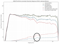
I see something similar (though not as pronounced) in Amir's Genelec S360 measurements (plotted with my script for consistency):


Note the peak near 900Hz in the negative vertical responses.
I didn't mean to suggest that either just that I haven't seen the same thing in your sim in real speakers. For me the Genelec looks like it is due to the crossover which is why I thought the same with your first images. They are different though when you look closely even though there is a resemblance.I'm not asserting that it will always significantly affect the woofer's directivity; merely that it does in this particular case.
When the driver and waveguide are the same size there can be "too much" directivity when combined and in that case there is a DI bump around the crossover frequency. Genelec uses 48dB symmetric crossovers in a lot of their newer speakers and this does not allow a blend in DI's to smooth the transition. When there is a bump (circled in your image attached) in both the SPDI and ERDI this is usually the cause and it is associated with a power response dip at the same point. That bump can also create a bit of a dip or flattening out on the lower side.
Your image from before shows an ERDI dip and power response bump which is the opposite phenomena and that is interesting.
Attachments
Again, what I'm talking about is not due to the crossover. Look at the peaking below the crossover point in the negative vertical angles. Both the S360 and my speaker show similar behavior in this region.For me the Genelec looks like it is due to the crossover which is why I thought the same with your first images.
Edit: This may be more clear than the contour plots or ER/SPDI curves.


Last edited:
- Home
- Loudspeakers
- Multi-Way
- Acoustic Horn Design – The Easy Way (Ath4)