

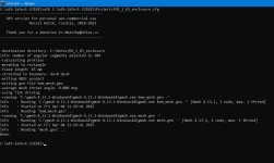
Does anyone know where the measurements of the waveguide went in the latest version?
In previous versions, when you ran the ath.exe binary, it would print out the size of the waveguide being simulated.
While I'm at it, has anyone bookmarked where the definition of the parameters are for a planar waveguide?
I believe it's R-OSSE, but I'm not 100% sure, and there doesn't appear to be any documentation of rectangular waveguides in the manual.
I have this snippet of code from one of Mabat's post, but I'm only guessing on what some of these parameters to. It's also very hard to Google them because they're a single character. (Google doesn't work well for short words.)
Here's the snippet from @mabat https://www.diyaudio.com/community/...-design-the-easy-way-ath4.338806/post-7163986
I answered one of my own questions.
Mabat indicates planar waveguides can be made with OSSE or R-OSSE, details are here:
Mabat indicates planar waveguides can be made with OSSE or R-OSSE, details are here:
Sure, just delete the first horn section from the script (Horn.Part:1), which is only a segment of a straight duct in that example (a = 0).
Then in the section that remains (you can rename it to Horn.Part:1, but it doesn't really matter), set 'a' to the desired values. This is set independently for H and for V, which are arbitrary OSSE profiles.
Then in the section that remains (you can rename it to Horn.Part:1, but it doesn't really matter), set 'a' to the desired values. This is set independently for H and for V, which are arbitrary OSSE profiles.
Re: Liquid nails Subfloor
It's worth a detailed look at the SDS (attached). In particular you don't want to inhale sanding dust from this stuff.
Patrick, do you use this with PLA in particular, or PET-G?
It's certainly cheap enough, a 10 oz tube is only $4.50 at the local home store.
It's worth a detailed look at the SDS (attached). In particular you don't want to inhale sanding dust from this stuff.
Patrick, do you use this with PLA in particular, or PET-G?
It's certainly cheap enough, a 10 oz tube is only $4.50 at the local home store.
Attachments
I mostly print in ASA
I occasionally print in PETG
I used it on both, but it works better on ASA I think
I never use PLA, it's too hot where I live (120F in the summer)
I occasionally print in PETG
I used it on both, but it works better on ASA I think
I never use PLA, it's too hot where I live (120F in the summer)
Change "abec.simtype" from 1 to 2
"type 1" is infinite baffle
"type 2" is freestanding
The various options are on page 22 of the manual, located in the "doc" folder of your ATH installation
"type 1" is infinite baffle
"type 2" is freestanding
The various options are on page 22 of the manual, located in the "doc" folder of your ATH installation
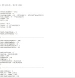
another question. why doesn't the "bottom" parameter change? i want the height of the cabinet to be 1300 mm. i tried different values, but the result is the same as in abec
Mesh.Enclosure = {
Spacing = 220,50,220,1300
Depth = 500
EdgeRadius = 30
EdgeType = 2
FrontResolution = 8,8,16,16
BackResolution = 20,20,20,20
}
Mesh.Enclosure = {
Spacing = 220,50,220,1300
Depth = 500
EdgeRadius = 30
EdgeType = 2
FrontResolution = 8,8,16,16
BackResolution = 20,20,20,20
}
Attachments
See page 56 of the manual:
"To use more quadrants we simply set the item Mesh.Quadrants to the desired value (see 4.1.4). For example, to simulate an enclosure in half-space symmetry, with a space left for a low frequency transducer under the waveguide, we need to use quadrants 1 and 4, i.e. set Mesh.Quadrants = 14:
That's a quote, but read the whole chapter, there's a lot of flexibility in the enclosures.
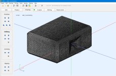
A620G2 is available for those brave enough (see Cults). Some datasheet/manual will hopefully follow.
Of course this one is meant for the biggest drivers that are able to utilize such a large device in the first place.

For 2" throats I'm finishing a spherical-wave plug as a Gen2 adapter. The idea is to transform a flat wavefront into sherical, improving the HF directivity considerably. Simulations are looking good but I won't buy Axi2050 just to verify (it really depends on how flat the input wavefront actually is). Otherwise, the 2" throats just start to beam too much at HF, IMO.
Of course this one is meant for the biggest drivers that are able to utilize such a large device in the first place.
For 2" throats I'm finishing a spherical-wave plug as a Gen2 adapter. The idea is to transform a flat wavefront into sherical, improving the HF directivity considerably. Simulations are looking good but I won't buy Axi2050 just to verify (it really depends on how flat the input wavefront actually is). Otherwise, the 2" throats just start to beam too much at HF, IMO.
Last edited:
I'll look at this.Does anyone know where the measurements of the waveguide went in the latest version?
In previous versions, when you ran the ath.exe binary, it would print out the size of the waveguide being simulated.
I already showed the A620G2 performance, but here it is again:

It really calls for being crossed as low as possible. With some of the bigger drivers 400 Hz should be no issue (the wave shaping plug promises even lower usage). The DI at 400 Hz is still pretty high but if you use the waveguide this low, you gain a very smooth and even curve(s) all the way up, and especially through the whole midrange.
Best used with a dipole bass cabinet, I would say.
Last edited:
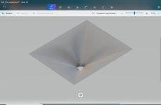
Good morning everyone!, I was wondering if with the latest version of ATH it is possible to import the profile into SolidWorks using coordinates. I have been looking into the manual and also trying the examples on page 167 of this same thread, but I haven’t had any luck. Could someone please guide me a bit? 🙂
The A620G2 feels like a nice foundation to build a MEH upon so please don’t limit your curiosity to a 2” entry.
And also consider adding the step files to the cult sales page as a bundle or separate sales item.
And also consider adding the step files to the cult sales page as a bundle or separate sales item.
It's not limited to 2" entry, as it's a regular Gen2 device compatible with all the existing adapters...
BTW, there's an ATH script file as a part of the package, so it's easy to get the profile coordinates to be used for whatever custom design.
BTW, there's an ATH script file as a part of the package, so it's easy to get the profile coordinates to be used for whatever custom design.
Is this true for older variants also now?BTW, there's an ATH script file as a part of the package, so it's easy to get the profile coordinates to be used for whatever custom design.
//
Does it make sense to create also a spherical-wave plug for a 1.4” driver to further improve its dispersion in the upper octave?For 2" throats I'm finishing a spherical-wave plug as a Gen2 adapter.
This is always worth a try, I would say. The worst thing that can happen is that it won't work 🙂
In my experience the radiation of the bigger drivers typically falls apart even before considerable beaming of a 1.4" throat has a chance to occur, so that it doesn't actually matter. It's just that the 2" throats start to beam really too low (to my taste, at least).
In my experience the radiation of the bigger drivers typically falls apart even before considerable beaming of a 1.4" throat has a chance to occur, so that it doesn't actually matter. It's just that the 2" throats start to beam really too low (to my taste, at least).
- Home
- Loudspeakers
- Multi-Way
- Acoustic Horn Design – The Easy Way (Ath4)