We are lucky that even standard pla that it’s easy to print can achieve a great result of stiffness will do it and post the results , with the parameters I used if I can help somebody, thanksA solid adapter should be to most sturdy (if you had the determination), but not really necessary, IMO.
I just took my 460G2 and knocked on it holding free air and another time damped by putting it on my leg. Very interesting how this soft external damping reduces knock-ringing to nearly 0. I was really suprised by this small experiment.
Maybe for final print I will design a small Support with some sylomer contacting the horn. This is available in various stiffnes.
Maybe for final print I will design a small Support with some sylomer contacting the horn. This is available in various stiffnes.

You could print something with TPUI just took my 460G2 and knocked on it holding free air and another time damped by putting it on my leg. Very interesting how this soft external damping reduces knock-ringing to nearly 0. I was really suprised by this small experiment.
Maybe for final print I will design a small Support with some sylomer contacting the horn. This is available in various stiffnes.
I'm going to try PCTG with the next adapter prototype.


Last edited:
Indeed I have a multi-material capable printer (Prusa XL). I already thought about making joints from TPU interlocked into the PetG. But that would be massive printing time and I did not yet figure out how to generate this type of mechanical interlocking between 2 printed materials in the slicer. If a local damping works that good I see no need to investigate this further.
You could just try to decouple the horn from the speaker cabinet , I had great success with sorbothane on a set of speakers , under their base , but an horn doesn’t produce much vibration
Hi @mabat,
Kindest regards,
M
Thank you for the explanation. I have a difficulty to envision the wavefront as both the phase plug and the diaphragm are frustoconical, so different points on the moving diaphragm will contribute, but I will take the approach of evaluating the air-channels' areas at planes perpendicular to the axial symmetry of the phase plug.It may not be easy to do, but imagine a wavefront traveling from the diaphragm through the phase plug. At any time instance, this wavefront will have some surface area. It is this area expansion through the phase plug you would be interested in. Even a crude estimation is still better than nothing. For one thing, you can at least measure/estimate the (total) input area and the overall length.
Kindest regards,
M
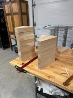
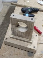
I started making sawdust fly on the wood portion of my horn - given how precise this all needs to be (9 miters with even a small amount of error adds up quick) this is really stressing my CNC skills! This is the first stack of rough blanks for the horn - each horn needs to have 18 pieces milled and assembled (9 petals, 2 pieces of wood per petal). This stack here represents 9 "tops" and 7 "bottoms" - hoping to mill the remainder tomorrow and then actually start shaping soon.
Attachments
Not sure if this is off topic or not, but is anyone working with ATH and ABEC/AKABAK to design coaxials or tri-axials?
It is simply the simulator not being able to come up with the right answer so it gives you garbage. There are a lot of little things that can add together and cause this sort of error at very high frequencies. I honestly would not worry about it, it may take a very long time to track all the issues and fix them to have a clean graph. Once you start to see sharp deviations up and down and general mayhem it is a big hint that those parts of the simulation are not accurate.My first assumption was rather the waveguide, as the wavelength must be very short, but could it be the diffraction of the high frequencies with mesh parts further out?
It is not real and will not be present like that in a real measurement. It bothered me to start off with now I just accept it unless I really need to know what the predicted directivity is like above 15K, perhaps in a speaker marketed to schoolchildren 🙂
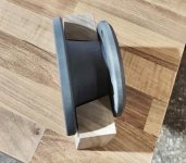
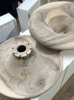
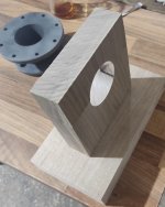
I have also made them out of wood, but sliced them differently. Here are some pics for reference, both raw and then with oil applied. These are made from solid walnut. I am working on their stand. They are now going to be held by two pieces of wood screwed around the adapter but I do not find this solution elegant.I started making sawdust fly on the wood portion of my horn - given how precise this all needs to be (9 miters with even a small amount of error adds up quick) this is really stressing my CNC skills! This is the first stack of rough blanks for the horn - each horn needs to have 18 pieces milled and assembled (9 petals, 2 pieces of wood per petal). This stack here represents 9 "tops" and 7 "bottoms" - hoping to mill the remainder tomorrow and then actually start shaping soon.
I will now make another pair, and add a straight portion on the backside to be able attach them to any stand.
Attachments

I'm really eager to see the first measurements, as these are probably the most accurate builds so far. Great work.
They must weight a ton, awesome jobI have also made them out of wood, but sliced them differently. Here are some pics for reference, both raw and then with oil applied. These are made from solid walnut. I am working on their stand. They are now going to be held by two pieces of wood screwed around the adapter but I do not find this solution elegant.
I will now make another pair, and add a straight portion on the backside to be able attach them to any stand.
Top job. Would you mind sharing the details esp how did you do about round overs. How much does it weigh? Looking forward to the measurements .I have also made them out of wood, but sliced them differently. Here are some pics for reference, both raw and then with oil applied. These are made from solid walnut. I am working on their stand. They are now going to be held by two pieces of wood screwed around the adapter but I do not find this solution elegant.
I will now make another pair, and add a straight portion on the backside to be able attach them to any stand.
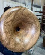
Contrary to what people might think, it is actually lighter than my 100% infill pla print. The wood I found was really dry so it does not weigh too much but it does not resonate with taps either.
The cnc is used on both sides, so no problems with roundovers. I just laminated wood thick enough to cover the depth of the horn and the cnc I used was capable of drilling the whole depth. So one side first and then the reverse. Some details on the cnc file for keeping it aligned/straight but not much else. This is without the throat adapter so I can variety of 3d printed throats and cd's with it.
I am finishing another project at the moment and I will delve into measuring and detailing the results with this one in a week or two.
The current stand is also being finalized
Attachments
I have expla,ned above, there are some short videos I have taken, maybe it will be more explanatory.@kodomo how did you fabricate the horn? It looks turned at first glance but the back leads me to thinik there was maybe some CNC / machining involved?
Attachments
Hi
any suggestions on best infill type for printing? Until now always used standard grid...but maybe someone experienced a better option?
any suggestions on best infill type for printing? Until now always used standard grid...but maybe someone experienced a better option?
- Home
- Loudspeakers
- Multi-Way
- Acoustic Horn Design – The Easy Way (Ath4)