Hi @mabat,

Kindest regards,
M
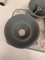
Thank you for the explanation. I do not know, if you saw the picture of the phase plug in the link I posted, but as you can (hopefully) see the width of the slots varies towards the outer diameter, so the area will vary accordingly. So, when you say "the areas of the air channels(s) at least at a few different distances from the diaphragm towards the exit" do you mean taking cuts at different surfaces perpendicular to the face of the driver and calculate the area at the surface?That would be very interesting to find out. I could then add this segment into the model to see what effect it has.
You would need to calculate the areas of the air channels(s) at least at a few different distances from the diaphragm towards the exit - the more data points the better.
Kindest regards,
M
This is a mesh issue / simulation artifact. Above 15KHz something is going wrong.Does anyone of you have an idea why the frequency response above 15kHZ looks like this? Is it a flaw in the cabinet design? Is it due to the mesh resolution or the Akabak
Almost the same thing happened to me a few times and it can be really tricky to find the cause. Getting exactly what is needed out of gmsh for manual drawings is a trial and error process.
My genuine solution is to change the range of the graph to 15K where the data is still valid and be done 🙂
You have a lot of resolution in the mesh so the solution is not more resolution. Avoiding thin triangles and making the triangles more even overall is usually the way to go for improvement with these sort of issues and that is how I have overcome it before. If I see it now I just truncate the graph and move on.

Did anyone consider printing pedals hollow with 2 small holes and fill in PU foam? In the end you get a sandwich structure very easily that is highly damped....worth a try?
I was always discouraged in the end by the added weight. It still seems to me that lightweight petals are more advantageous. It would need to be some kind of light foam but that's not easy to work with - much easier said than done.
I already thought about some external "dampers" - for instance some rods pushed against the waveguide from the back, via a piece of some damping material. But the hollow petals (with a sparse infill only) really don't ring that much if they are thick enough. Overall, I don't think this is a big issue - it's certainly not easy to actually measure anything.
I already thought about some external "dampers" - for instance some rods pushed against the waveguide from the back, via a piece of some damping material. But the hollow petals (with a sparse infill only) really don't ring that much if they are thick enough. Overall, I don't think this is a big issue - it's certainly not easy to actually measure anything.
I've printed few different freestanding waveguides in few different composition trying to address acoustic sound of the object itself, but all of them have had a "bell mode" of sorts. The mouth portion is ringing and it is easy to detect by just tapping the device with hand, rings very easily. I haven't been able to make any effective CLD or other structure solutions yet, to tame these. I haven't tried filling the petals afterwards.
Most effective way to dampen is just touch the mouth with hand and any bell mode is completely gone so I'm with mabat on this. Without such lossy connection you can literally tune the ringing of such device by tightening nuts/bolts that connects it to a driver/mount, and the worse it seems to get the more "rigid" the thing becomes, so lossy connections everywhere works better in this regard rather than tight and secure. That said, while a device has this kind of modes they don't seem to be that audible in use, it's not just very good quality assurance have plastic looking and feeling thing, so better do something about it if possible.
Most effective way to dampen is just touch the mouth with hand and any bell mode is completely gone so I'm with mabat on this. Without such lossy connection you can literally tune the ringing of such device by tightening nuts/bolts that connects it to a driver/mount, and the worse it seems to get the more "rigid" the thing becomes, so lossy connections everywhere works better in this regard rather than tight and secure. That said, while a device has this kind of modes they don't seem to be that audible in use, it's not just very good quality assurance have plastic looking and feeling thing, so better do something about it if possible.
Last edited:
It may not be easy to do, but imagine a wavefront traveling from the diaphragm through the phase plug. At any time instance, this wavefront will have some surface area. It is this area expansion through the phase plug you would be interested in. Even a crude estimation is still better than nothing. For one thing, you can at least measure/estimate the (total) input area and the overall length.Thank you for the explanation. I do not know, if you saw the picture of the phase plug in the link I posted, but as you can (hopefully) see the width of the slots varies towards the outer diameter, so the area will vary accordingly. So, when you say "the areas of the air channels(s) at least at a few different distances from the diaphragm towards the exit" do you mean taking cuts at different surfaces perpendicular to the face of the driver and calculate the area at the surface?
edit time over, wanted to add that in general, printing big waveguide in parts isn't exactly fun, easily many hours just tweaking printer settings, several prototypes to weed out possible issues, then surface finishing and all kinds of small stuff, adjusting tolerances, messing up with the glue and so on. I've lost tens of hours trying to print such parts that could skip all the post processing like sanding and filling and painting 😀 One can tweak the acoustic sound of the device itself, how light is reflected of it and so on and when you turn the part on printer bed it's back to tweaking settings and so on, million things besides the main function providing nice sound. Still, printing in parts is about the easiest way to get hold of such thing. So, have fun everyone!
I do have a few petals/segments laying around that I intend to fill when I decide on a suitable filling material. If using anything expanding I will make certain to add a lot of holes to let the excess PU escape and hopefully not damage/warp the petal. Its probably a good idea to assemble the horn before adding fill.Did anyone consider printing pedals hollow with 2 small holes and fill in PU foam? In the end you get a sandwich structure very easily that is highly damped....worth a try?
But have you tried assembling such a segmented horn? Using 4 outer layers and around 10-15% infill I find the finished horns rather "dead" and get the impression that they are rather well damped. Needs to be verified by accelerometer. This is with PLA+ 0.2 layers glued with CA.
I didn’t expect such good result , I had some little failures and tried different infill as for me I did print the petals now with various try from 10-17% gyroid infill and they take a lot of time , just 13 hours for 3 petals at 17% infill weighting just 480g circa for 3 petals which is plenty enough as they are very sturdy , I did use 3 wall loops and the just standard 20mm profile on the Bambu lab , and I am not an experienced printer myself , did try printing the base that is almost empty with the lightning infill but it has those 2 lines nothing crazy , it would have been better at 100% infills but it would take 700 grams and 12 hours which I will do soon , just regular pla I think it’s fine , there is pla + which should be a little bit stronger but we are there in differences , the thing is that pla is the one Easyer to print , I still not have bought the BMS adapter file and I don’t know the weight of the adapter at 100% infill would be
Attachments
I wouldn't use a solid (100%) infill, maybe except some really small parts (throat rings, etc). Using something like 50% seems even a better solution to me. I still see the infill also as a damping structure, kind of.
All my prototypes use only a very sparse infill (typically the "support cubic", the most economic), including the adapters. I use a 0.6mm nozzle, 2 perimeters. And I could well imagine keeping it like that.
All my prototypes use only a very sparse infill (typically the "support cubic", the most economic), including the adapters. I use a 0.6mm nozzle, 2 perimeters. And I could well imagine keeping it like that.
Last edited:
My experience as well. Epoxy coating also adds to that.Using 4 outer layers and around 10-15% infill I find the finished horns rather "dead" and get the impression that they are rather well damped.
This is a mesh issue / simulation artifact. Above 15KHz something is going wrong.
Almost the same thing happened to me a few times and it can be really tricky to find the cause. Getting exactly what is needed out of gmsh for manual drawings is a trial and error process.
My genuine solution is to change the range of the graph to 15K where the data is still valid and be done 🙂
You have a lot of resolution in the mesh so the solution is not more resolution. Avoiding thin triangles and making the triangles more even overall is usually the way to go for improvement with these sort of issues and that is how I have overcome it before. If I see it now I just truncate the graph and move on.
I like to hear that 🙂My genuine solution is to change the range of the graph to 15K where the data is still valid and be done 🙂
I also think it is a mesh (resolution) error or something in that category.
The first thing I tried was my measurement setup in AKabak with a simple square housing and mabak's waveguide. I did not have these errors there.
Afterwards I made another attempt with my model and a lower, but more evenly distributed resolution and one with an even higher resolution only in the entire front area (the calculation took 2h XD) and with the higher resolution the errors around 20kHz were almost completely gone. With a lower resolution the results were even worse
Are these artifacts perhaps due to the very round front, which requires a much higher resolution than a flat baffle with one phase?
My first assumption was rather the waveguide, as the wavelength must be very short, but could it be the diffraction of the high frequencies with mesh parts further out?
Ok thank you mabat , for the throat adapter should I go for 50% infill or denser ? The rest will go for 50%, and as you suggested the smaller parts like the ring at 100%I wouldn't use a solid (100%) infill, maybe except some really small parts (throat rings, etc). Using something like 50% seems even a better solution to me. I still see the infill also as a damping structure, kind of.
All my prototypes use only a very sparse infill (typically the "support cubic", the most economic), including the adapters. I use a 0.6mm nozzle, 2 perimeters. And I could well imagine keeping it like that.
Hi everyone
I need some guidance as to how to proceed with my horn speaker build. I've modeled the A460G2 in Akabak and it looks extremely good, and, separately modeled the bass unit. The A460G2 results are based off a simple diaphragm (as per Mabat's ABEC export files) but I think I should add a CD via the LEM to get a more realistic response curve that I can then match with that from the bass unit.
My questions are:
PA
I need some guidance as to how to proceed with my horn speaker build. I've modeled the A460G2 in Akabak and it looks extremely good, and, separately modeled the bass unit. The A460G2 results are based off a simple diaphragm (as per Mabat's ABEC export files) but I think I should add a CD via the LEM to get a more realistic response curve that I can then match with that from the bass unit.
My questions are:
- Should I add the CD in the LEM to determine cross-overs or just build it and measure?
- If I should replicate the CD what TS parameters should I use for the SBA Rosso 65CDN-T?
- Is a cross-over around 700Hz realistic or do I, in practice, need to go higher?
- What cross-overs are people using with the A460G2?
PA
But why? Are you not satisfied with your current results? I guess it will prolong the print times considerably. For the adpater, I would probably rather increase the number of perimeters ("walls").Ok thank you mabat , for the throat adapter should I go for 50% infill or denser ? The rest will go for 50%
I am very satisfied, and I will follow your guidelines by increasing the walls , and stick to 50% I didn’t understand the other day thought that you’d have used like 100% infill
A solid adapter should be to most sturdy (if you had the determination), but not really necessary, IMO.
If you're already satisfied, why change it.
If you're already satisfied, why change it.
@PrinceArnold - I wouldn't bother with further simulations at all. Just build it and measure everything... There's not much you could really improve anyway.
With almost any 1.4" driver, 700 Hz is a safe xover frequency.
With almost any 1.4" driver, 700 Hz is a safe xover frequency.
- Home
- Loudspeakers
- Multi-Way
- Acoustic Horn Design – The Easy Way (Ath4)