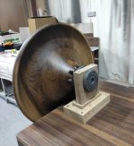

This is for the LaVoce and the adapter is the one that was made for it. I have tried extended adapter and heard/measured the potential for having lower cutoff but then again I believe LaVoce would be better and less stressed if used above 800hz, it is still pretty low for a 1" so I am happy. To not confuse when I say use over 800hz I do not mean my crossover point is 800hz, it will be lower and my aim is to cross it around 680hz
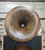
Looking at the second photo above, I can't get rid of the impression that the adapter exit diameter doesn't match the waveguide throat... Please, tell me it's something else 🙂
Last edited:
I'm actually confused... what do you mean?To not confuse when I say use over 800hz I do not mean my crossover point is 800hz, it will be lower and my aim is to cross it around 680hz
//
This is for the LaVoce and the adapter is the one that was made for it.
https://at-horns.eu/gen2m.html#df10171k
Maybe a trick of light, it wasn’t screwed properly it could be that tooLooking at the second photo above, I can't get rid of the impression that the adapter exit diameter doesn't match the waveguide throat... Please, tell me it's something else 🙂
The aim for the crossover is 680hz lr4, so the f0 will be around 800hzI'm actually confused... what do you mean?
//
found an interesting video for 3 printed speakers, the watch is reccomended
Thats really not have "we" use to express this.. but good you clarified it ;-)The aim for the crossover is 680hz lr4, so the f0 will be around 800hz
XO freq is always Fo. Ever was, ever will be....
//
I don't know what's that either, but I understood kodomo's f0 as the frequency where there's already no attenuation (0 dB) from the filter (which would be problematic but good enough for an intuitive understanding). But that would still not be a crossover frequency, which, in my book, is the frequency where the pressures from both units are the same - at least that's probably the best general definition I would come up with.
Last edited:
That is why I did not say crossover frequency is 800hz. I meant where there is no attenuation like Mabat have guessed. By f0 I mean 0db, crossover frequency for a LR filter would be its f6 (-6db point). Maybe this is not the terminology used hence the confusionThats really not have "we" use to express this.. but good you clarified it ;-)
XO freq is always Fo. Ever was, ever will be....
//
So I finally got around and modified my optimizer script to store the parameters in a database instead of the file names, as the file names got too long for both ath and ABEC. The sudden motivation came from the 5950X that replaced my 3700X and ChatGPT adding the o3 mini model to the normal user tier.
A few dozen pages back there was some discussion that the ideal exit angle of a waveguide is relative to the tweeter geometry, so it does not make sense to rate the level of the DI curve but just accept whatever works best. All I'm rating now are the horizontal and vertical frequency responses.
Still, I have space left on my results pictures. What would you recommend to put in the lower left? Impedance?

And also, I'm still randomly getting flipped faces in my simulations. Given that I doubled my simulation speed with the new CPU, I think I could increase the resolution of the simulations a little bit. Which parameter to change though?
A few dozen pages back there was some discussion that the ideal exit angle of a waveguide is relative to the tweeter geometry, so it does not make sense to rate the level of the DI curve but just accept whatever works best. All I'm rating now are the horizontal and vertical frequency responses.
Still, I have space left on my results pictures. What would you recommend to put in the lower left? Impedance?
And also, I'm still randomly getting flipped faces in my simulations. Given that I doubled my simulation speed with the new CPU, I think I could increase the resolution of the simulations a little bit. Which parameter to change though?
Mesh.Enclosure = {{
Spacing = 32,32,32,32
Depth = 160
EdgeRadius = 32
EdgeType = 1
FrontResolution = 7,7,7,7,
BackResolution = 24,24,24,24
}}
Mesh.Quadrants = 1 ; =1 for 1/4 symmetry,
;Mesh.VerticalOffset = 80
Mesh.AngularSegments = 64
Mesh.LengthSegments = 14
Mesh.SubdomainSlices =
Mesh.ThroatResolution = 3
Mesh.MouthResolution = 6
Mesh.InterfaceResolution = 5
Mesh.RearResolution = 20
Occurs sometimes. You want to vary Mesh resolution settings, Mesh lenght/angular segments, and there is this Z coordinates parameter I don't remember the proper name.
Ok, so not nearly as good as Kodomo's effort but I finally got some sound out of the A460g2.

- Home
- Loudspeakers
- Multi-Way
- Acoustic Horn Design – The Easy Way (Ath4)