@mabat Quick question about the SB Rosso adapter - it appears to me that it is an insert into the CD drivers much like your Extended throat BMS 4554 kit; however, it looks like the application is a bit different, as there is no "screw" between the throat adapter, the driver flange adapter and the throat adapter before the petals. Any suggestions as to how to do all this without the "screw" application, or how you did it specifically with your model?
I made now a LF horn matching the 460G2. Modeled with the drivers curvature. Using ATH made this a fast proceeding task ;-)
I want to simulate with this in Akabak for XO and overall performance.. Before I mesh it with GMesh I need to draw the interfaces. But....where to place them? 1 interface or 2? Until now I only had one driver/horn....
It doesn't look like you want to simulate it on an infinite baffle, consequently, I don't think you'll need interior subdomains or interfaces. I think you'll only need one exterior subdomain in your case. As an option you could split your 3D model in half along the Y-axis and using the "Symmetry X" option (Global->Dim, Sym, and BEM...->Symmetry drop down) to speed up your simulation but it isn't necessary.
@mjhara - I'm not sure I understand your question/intent. Yes, the ROSSO adapter has a ring plug to be inserted into the driver and this then connects via a "standard" adapter to a Gen2 horn -


(There's a centering ring on the front side of the adapter.)
I haven't tried yet a more extended adapter, like the one for the BMS drivers. It could work, or not, that would need to be tested.
Measured with A520G2 - already a "serious" performer:

All these bigger drivers have incredible power. May never be as smooth in the top octave as the best of the smaller ones but if you're after really loud and lifelike, this certainly shouldn't disappoint.
(There's a centering ring on the front side of the adapter.)
I haven't tried yet a more extended adapter, like the one for the BMS drivers. It could work, or not, that would need to be tested.
Measured with A520G2 - already a "serious" performer:
All these bigger drivers have incredible power. May never be as smooth in the top octave as the best of the smaller ones but if you're after really loud and lifelike, this certainly shouldn't disappoint.
Last edited:
Thanks for the hint. Maybe it's worth a try, this seems doable. I'm a bit sceptical that it would hold the parts strongly enough so that no other means of securing would be needed, but I'll try.Ball and socket joint
My imagination tells me that a couple of these along the edge would be enough to align the parts accurately, and hold them together while the glue dried without tape or clamps. I'm useless with CAD (that's a future phase of my self-education), but it wouldn't seem all that hard to implement.
@mabat I guess the question is this - on the BMS 4664 adapter you have a small gasket between the throat adapter and the driver insert, and there the friction between the driver insert and the adapter is employed with a "screw" connection between an independent driver flange, whereas this one doesn't appear to have or maybe need that gasket? I guess another way of asking or thinking about this is - would there be any disadvantage to printing the CD insert and throat adapter as one piece, and just inserting it all together? I would imagine it would make a better transition between the two, although the fitting/sanding part would be much more difficult. Just thinking out loud.
I did my first couple of prints to get the form / aesthetic right for the transition to the wooden horn. I'm also integrated the Joseph Crowe rear chamber for the SB Audience - he claims it lowers the FS to 240 Hz and smooths out the midrange. I don't have time or the knowledge to validate that, but it looks nice. It has been a lot of fun so far -
I did my first couple of prints to get the form / aesthetic right for the transition to the wooden horn. I'm also integrated the Joseph Crowe rear chamber for the SB Audience - he claims it lowers the FS to 240 Hz and smooths out the midrange. I don't have time or the knowledge to validate that, but it looks nice. It has been a lot of fun so far -
Attachments

Also - based on my hearing tests my upper limit right now is about 15 Khz anyway, so I doubt I'll be missing much up there 🙂. If I need to, I always thought I could ad an omnidirectional supertweeter to the mix but I doubt I'll miss it.
Regarding the gasket, I think this was solved very elegantly by TNT:
I cut a circle in the CD gasket and removed it so that the insert could meet the metal of the CD. And I put the bug screen between the horn mount and the insert - worked perfectly. So no wasp nests 🙂
//
As you make it for yourself, always do whatever you feel should work well. I'm sure there are many ways how to do it.
- I'm really looking forward to your measurement outcomes.
OK - I did.Honestly, I don't remember, like at all. I think you will need to apply some creativity.
I cut a circle in the CD gasket and removed it so that the insert could meet the metal of the CD. And I put the bug screen between the horn mount and the insert - worked perfectly. So no wasp nests 🙂
//
As you make it for yourself, always do whatever you feel should work well. I'm sure there are many ways how to do it.
- I'm really looking forward to your measurement outcomes.
Thanks! I think I figured out a work around that will solve some of the assembly and sequencing issues - I'm going to print the CD insert separately so I can fit it independently - then, after I get a satsifactory fit, I'll dry fit it with the throat / horn adapter to make sure everything is kosher. Once that is done, I'll remove the throat insert, fuse / glue it to the throat/horn adapter, THEN paint, then assemble. This way I'll get a good, air-tight seamless transition, avoid having to extensively tape/mask non-painted joints, and I can still fit the CD insert independently to avoid having to try to sand that to fit. Seems like this might be a good solution so far as I can tell.
Hi folks,
I'm trying to create a small waveguide for the Bliesma t25b. I have already done about 50 simulations and the best attempt is still my first 😀.
Can you tell me the best way to get a more even off-axis response at higher frequencies?
Are my values for the simulation ok or would you say that there is a bigger design (or thinking error)?
Is it possible that there is a slight plateau in the 12-18khz range because the Bliesma T25 has an inverse surround?


I would be grateful for any information
best regards poiy
I'm trying to create a small waveguide for the Bliesma t25b. I have already done about 50 simulations and the best attempt is still my first 😀.
Can you tell me the best way to get a more even off-axis response at higher frequencies?
Are my values for the simulation ok or would you say that there is a bigger design (or thinking error)?
Is it possible that there is a slight plateau in the 12-18khz range because the Bliesma T25 has an inverse surround?
I would be grateful for any information
best regards poiy
;Bliesma T25B
zoff -0.05
point p1 4.239 0 2
point p2 0 12.5 0.5
point p3 -1.003 13.76 0.5
point p4 0 15.02 0.5
point p5 0 15.20 1
cpoint c1 -16.311 0
cpoint c2 0.29 13.76
arc p1 c1 p2 1.0
arc p2 c2 p3 0.75
arc p3 c2 p4 0.25
line p4 p5 0
line p5 WG0 0
; --------------------------------------------------------------
; Horn geometry
R-OSSE = {
R = 40
r0 = 15.2
a = 60
a0 = 13
k = 1
m = 1
r = 1
b = 0.03
q = 5
}
; --------------------------------------------------------------
; Acoustic Source - Bliesma T25B
Source.Contours = C:\Program Files\ath4\cfg\dome.src
Source.Velocity = 2
; --------------------------------------------------------------
; Transducer LE Model
; LE = <LE_script_file>
; --------------------------------------------------------------
; Basic Geometry
Morph.TargetShape = 0
Mesh.AngularSegments = 32
Mesh.LengthSegments = 20
Mesh.ThroatResolution = 5.0
Mesh.InterfaceResolution = 8.0
Mesh.InterfaceOffset = 5.0
; --------------------------------------------------------------
; General Simulation Parameters
ABEC.SimType = 1
ABEC.f1 = 500 ; [Hz]
ABEC.f2 = 20000 ; [Hz]
ABEC.NumFrequencies = 40
ABEC.MeshFrequency = 1000 ; [Hz]
; --------------------------------------------------------------
; Observations
ABEC.Polars:H_SPL = {
MapAngleRange = -90,90,19 ; 0 – 180 deg with 5 deg step
NormAngle = 0 ; [deg]
Distance = 3 ; [m]
Offset = 20
}
ABEC.Polars:V_SPL = {
MapAngleRange = -90,90,19 ; 0 – 180 deg with 5 deg step
NormAngle = 0 ; [deg]
Distance = 3 ; [m]
Inclination = 90
Offset = 20
}
; --------------------------------------------------------------
; Program output
Output.ABECProject = 1
Output.STL = 0
; --------------------------------------------------------------
; Reporting
Report = {
Title = "horn example"
Width = 1600
Height = 900
}
Here's something ultra small and ultra smooth (⌀58 x 5 mm):


Code:
; circular-arc profile
Throat.Profile = 3
Throat.Diameter = 30.4
Length = 5
Coverage.Angle = 70
CircArc.TermAngle = 1

Source.Contours = {
    zoff -0.05
    point p1 4.239 0 2
    point p2 0 12.5 0.5
    point p3 -1.003 13.76 0.5
    point p4 0 15.02 0.5
    point p5 0 15.20 1

    cpoint c1 -16.311 0
    cpoint c2 0.29 13.76

    arc p1 c1 p2 1.0
    arc p2 c2 p3 0.75
    arc p3 c2 p4 0.25
    line p4 p5 0
    line p5 WG0 0
}

Source.Velocity = 2   ; axial motion

Mesh.AngularSegments = 8
Mesh.LengthSegments = 16

ABEC.SimType = 1
ABEC.SimProfile = 0
ABEC.f1 = 200
ABEC.f2 = 20000
ABEC.NumFrequencies = 60
ABEC.MeshFrequency = 45000

ABEC.Polars:H_SPL = {
    MapAngleRange = -90,90,19 ; 0 – 180 deg with 5 deg step
    NormAngle = 0 ; [deg]
    Distance = 3 ; [m]
    Offset = 20
}

Report = {
  Title = "T25B"
  NormAngle = 1000
  Width = 1200
  Height = 800
}
Last edited:
That's for T25B already (it uses your source definition).
Only beware that an enclosure will more or less ruin this 🙂
But you can easily try to make it larger, here's the documentation -

Only beware that an enclosure will more or less ruin this 🙂
But you can easily try to make it larger, here's the documentation -
Last edited:
You did an awesome job. Do you have a picture of the horn you printed? I got a bambulab printer myself, and this bms caught me the attention because its only 170€ not bad!!!!I've printed, sanded, assembled and tested the 5530ND and here are the spectacular results (as expected 😀):
View attachment 1407743
No smoothing, 6 ms window. With no windowing and 1/6th octave smoothing:
View attachment 1407745
Distortion on axis with 2nd order BW HP at 600 Hz and EQd flat:
View attachment 1407746
Impulse response on axis looks like this:
View attachment 1407744
Probably the best device I've measured. Great work Marcel and everyone else involved!
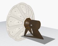
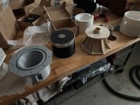
How much pla filament did you use for 1 horn? I would love to build it for fun!Well, printing and gluing the 460G2 was easier than I was expecting. Am now waiting for the SBA Rosso CD and will need to design an build a stand so I can test it out.
Things to note:
The finish is really good. After testing I hope to use a filler to fill the small gaps between petals and then paint.
- there is a little bit of shrinkage in the petals so they do not fit perfectly together. This could be my fault or a characteristic of 3d printing PLA. It did have the benefit of making fitting a little easier!
- I needed to print another part for the assembly jig to hold the petals in place (is the cap with the wing nut next to the horn)
- Slow acting epoxy, the slower the better, is the way to go.
Achieving good test results is critical for me to proceed to building the case for the woofer.
View attachment 1413073
I struggle to get Ath to draw the kind of circular radius that I want (possibly an issue with the operator) but I can easily draw and simulate them myself manually. I drew one very similar to this for the T25B for another member and the result was acceptable. Enclosure width/depth and baffle edge has to be considered carefully because it has a big impact on theses small guides without significant directivity.Unfortunately, I didn't manage to maintain the off-axis behavior with a slightly larger waveguide. Maybe I'll just use the waveguide from HiFiCompass.Anyway, thanks for your help
https://www.diyaudio.com/community/threads/t25a-simple-waveguide-profile.423131/#post-7912455
Anyway, this should help to smooth out the last bits at HF for the T25B -
(It's ⌀68 x 7 mm, i.e. the same diameter as the original mounting flange of the tweeter.)

It's a circular arc with radius r = 28.5376mm with the center at [x,y] = [-21.5376, 33.8224]mm.
(It's ⌀68 x 7 mm, i.e. the same diameter as the original mounting flange of the tweeter.)
It's a circular arc with radius r = 28.5376mm with the center at [x,y] = [-21.5376, 33.8224]mm.
Code:
; circular-arc profile
Throat.Profile = 3
Throat.Diameter = 30.2
Length = 7
Coverage.Angle = 69.5
CircArc.TermAngle = 0

Source.Contours = { ; T25B
  dome p1 25 4.24 2.5 -1 3 1
  line p1 WG0 0
}For the T25A it's a bit more subtle (the taller dome wants to radiate wider), I'll try to run an optimization.

Are the T25B and T25A profiles in the screenshots are accurate ?
I would like to use it like a basis in Fusion.
Beacause I don't konw ATH, how to read the contours numbers?
Thanks,
Thomas
I would like to use it like a basis in Fusion.
Beacause I don't konw ATH, how to read the contours numbers?
Source.Contours = { ; T25B dome p1 25 4.24 2.5 -1 3 1 line p1 WG0 0}
Thanks,
Thomas
As for the dome macro: https://www.diyaudio.com/community/...-design-the-easy-way-ath4.338806/post-7353694
I rely on third-party data here, as I don't possess these tweeters.
I rely on third-party data here, as I don't possess these tweeters.
- Home
- Loudspeakers
- Multi-Way
- Acoustic Horn Design – The Easy Way (Ath4)