I remember that I had a pair of Morel MDT33s, always thought they were protruding too much…
https://www.madisoundspeakerstore.c...8-et338-104-and-supreme-st1048-st1108-st1308/
https://www.madisoundspeakerstore.c...8-et338-104-and-supreme-st1048-st1108-st1308/
as far as I remember in @augerpro's WG thread there were simulations of a step near the joint of WG to surround, which in my opinion is a similar solution to covering the surround. Both are ways to "connect" the idealized WG surface shape to the tweeter dome edge.I tried to cover the surround in different ways in the sims, but it always came out worse than without.
and here is my very rough measured comparison of WG-surround-joint variants:

I assume the notches are created by distance from tweeter dome to the WG start.
I am happy to be corrected, of course!

But a hemisphere doing a pistong movement would not add much from it's sides - right...(as it is not getting wider as it vibrates) so all domes rely on bending wave "break up" for its dispersion I would think... and the result of that you cant tell by looking att the shape... problematic...
//
I've generally found that soft domes work really well on waveguides. Bruce Edgar found the same.
I talked to Andrew Jones about this, and he theorized that at high frequencies, soft domes basically act like ring radiators. The tip of the dome is mostly decoupled from the rest of the diaphragm, because the soft material isn't rigid enough to behave "ideally" above 10khz.
Hence, the reason that every one of his speakers that used a waveguide use a soft diaphragm, except for his TAD speakers, which were beryllium.
Well a ring radior differ in the sense that its tip/center don't "slouch" around - as it dosen't have one 🙂 ... bending wave radiators can sound wonderful.
//
//
True.
I can't speak for Jones, and it's been a few years. But IIRC, what he liked about traditional soft domes is that you get the behavior of a ring at high frequency, when a ring works really well. But at lower frequencies, like 2khz, you get the advantage of a higher SD. It's a subtle difference in SD, only about 25%, but it's something.
Plus, there are just a lot more domes to choose from.
I'm not a doctor. 0 patients. 😁Add patience 😉
//
Can someone confirm that it is not possible to have ATH extract the horizontal and vertical SPL from the ABEC results?
I'd really prefer not having to do that.😅
You can export all the defined polars into separate text files - search for FRDExport in this thread.
This will be also handy:
This will be also handy:
Here's a recap regarding phase data:
- If you specify Distance in ABEC.Polars, FRs are simply calculated at that distance from the origin and VACS phases include all the propagation delays (may seem "weird" due to wrapping but they are correct). Ath currently removes the delay corresponding to this distance automatically in the FRD export function. This is the recommended way how to obtain the data for a crossover simulation. Don't use any PhaseComp unless you know what you're doing.
- If you don't specify Distance in ABEC.Polars, ABEC...
Last edited:
BTW, a nice and smooth HF dispersion can be apparently obtained even with something as small as this.
- This a mesh of the Sica LP110 dome, so you get the picture of the overall size:

And this is the prediction for an infinite baffle (just a random try, no optimization yet):

This is the dome model used (Sica Z009240):
Source.Contours = {
dome WG0 29 8.5 3.75 1 5 2
}
Source.Velocity = 2
- This a mesh of the Sica LP110 dome, so you get the picture of the overall size:
And this is the prediction for an infinite baffle (just a random try, no optimization yet):
This is the dome model used (Sica Z009240):
Source.Contours = {
dome WG0 29 8.5 3.75 1 5 2
}
Source.Velocity = 2
Last edited:
The corresponding 3D model -
a) bare dome in a flat baffle

b) with a 5mm deep "waveguide" (see the -6 dB line above 5 kHz)

Below ~5 kHz I believe much is dependent on the shape of the enclosure.
Here the source was placed in the center of a small panel, for simplicity -


a) bare dome in a flat baffle
b) with a 5mm deep "waveguide" (see the -6 dB line above 5 kHz)
Below ~5 kHz I believe much is dependent on the shape of the enclosure.
Here the source was placed in the center of a small panel, for simplicity -
Last edited:
I have also some Morel 1" tweeters with concave surrounds. Those might be perfect for this, allowing tighter spacing as well (e.g. the MDT-39).
And something a bit different -


Some ideas come to mind but I need to try them first 🙂
Some ideas come to mind but I need to try them first 🙂
No so fast..Those might be perfect for this
convex surround:
concave surround:
Apparently, different surrounds need separate optimizations.
Scan-Speak provides CAD models, downloadable from the product pages. Taking a look at the D2608/913000 https://www.scan-speak.dk/product/d2608-913000/ (similar proportions of dome and surround as on the Sica tweeters?), the profile of the faceplate has a step going above the height of the surround and also tapers inwards.
The D2604/830000 and D2604/833000 seem to have quite a bit wider surround, but there are some measurements of these on a waveguide (plus adapter plate, so with factory faceplate not removed?), as well as the Peerless DX25TG09-04 which supposed to be almost the same tweeter but shows a bit smoother FR.
https://heissmann-acoustics.de/en/test-vifa-xd-270-f4-waveguide-wg-300/
https://heissmann-acoustics.de/en/test-scan-speak-discovery-d2604-830000-mit-wg-pct-300-wg-300/
https://heissmann-acoustics.de/en/test-scan-speak-discovery-d2604-833000-p-audio-pct-300/
Attachments
Hi
Some time ago I tested the DCX464 with a ATH. I was really impressed. Unfortunatrly the fact that it is a 1,4" driver and that it has a nasty internal resonance (with steep XO not really an issue) made me think more about it.
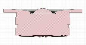
I disassemble and found how they combine HF and LF section. The picture should explain it well.
I already 3D scanned the insert and the driver housing. Now I am re-drawing it. Goal: let the horn start at any diameter I choose right where the LF-Slots come together with the HF. I could also combine the LF a few mm later....
All that is necessary is to exchange the silver insert and make a tube-insert for the outer part. Maybe it gets more clear after first print ;-)
@mabat : I need a ATH profile down to 16-20mm throat diameter I would say best for the 480? If I purchase from cults could you give me the necessary extension?

Some time ago I tested the DCX464 with a ATH. I was really impressed. Unfortunatrly the fact that it is a 1,4" driver and that it has a nasty internal resonance (with steep XO not really an issue) made me think more about it.
I disassemble and found how they combine HF and LF section. The picture should explain it well.
I already 3D scanned the insert and the driver housing. Now I am re-drawing it. Goal: let the horn start at any diameter I choose right where the LF-Slots come together with the HF. I could also combine the LF a few mm later....
All that is necessary is to exchange the silver insert and make a tube-insert for the outer part. Maybe it gets more clear after first print ;-)
@mabat : I need a ATH profile down to 16-20mm throat diameter I would say best for the 480? If I purchase from cults could you give me the necessary extension?
Check the drawing in the review here then my idea should become more clear. Start where LF and HF meet:
https://audioxpress.com/article/tes...h-powered-coaxial-compression-driver-and-horn
https://audioxpress.com/article/tes...h-powered-coaxial-compression-driver-and-horn
Was a mis-match between the entry diameter of the horn and the exit diameter of the driver what caused this "nasty acoustic resonance"?Unfortunatrly the fact that it is a 1,4" driver and that it has a nasty internal resonance...
No that was OK. If you check the reviews (e.g. Joseph crowe) you see some peak right after the xo point. Seems to be something internal. In real application it should not matter....but I know it is there 🤔😱. I assume with a different combiner-section this might change. In their new version (dcx354) it seems to be gone, too.
Edit: I was wrong. also visible at the 354
Edit: I was wrong. also visible at the 354
Olombo wrote: "If you check the reviews (e.g. Joseph crowe) you see some peak right after the xo point."
You mean the midrange diaphragm's impedance and frequency response peaks just north of 5 kHz? I have been under the impression that was diaphragm breakup, in which case a different combiner-section geometry probably wouldn't make much difference. But I could be wrong.
You mean the midrange diaphragm's impedance and frequency response peaks just north of 5 kHz? I have been under the impression that was diaphragm breakup, in which case a different combiner-section geometry probably wouldn't make much difference. But I could be wrong.
Probably. Although this ring diaphragms are that rigid and stiff....
Well we will see soon. Maybe it helps maybe not. In any case it will lead to more uniform dispersion in upper region since I can start with smaller throat diameter. If this is then worth the effort....🤷♂️
Well we will see soon. Maybe it helps maybe not. In any case it will lead to more uniform dispersion in upper region since I can start with smaller throat diameter. If this is then worth the effort....🤷♂️
"In any case it will lead to more uniform dispersion in upper region since I can start with smaller throat diameter. If this is then worth the effort....🤷♂️"
Ah, this makes sense.
I looked at the spec sheets for the 8 ohm and 16 ohm versions of the DCX464. That peakage occurs at a slightly higher frequency with the 16-ohm version, which imo would be expected if it's a breakup mode because the thinner and therefore lighter voice coil wire would push the breakup frequency slightly higher. So imo this is evidence of diaphragm breakup being the cause.
On the other hand if it was an internal airspace resonance, the frequency would not have changed from the 8-ohm to the 16-ohm version because the internal geometry is identical for both versions.
- Home
- Loudspeakers
- Multi-Way
- Acoustic Horn Design – The Easy Way (Ath4)