This is the easier to assemble version?ATH E460G2 is available now.
Bugger. I just bought the old version two days ago thinking it had been updated to this! 😂
E460G2 is based on A460G2, but it goes through a hexagonal inner shape, so it's different (in the same way as E/A520G2). But it should be fairly easy to assemble, using splines that proved to work well.

I already thought about making a new version of the A460G2 kit (also using splines), but haven't started working on that yet.
I already thought about making a new version of the A460G2 kit (also using splines), but haven't started working on that yet.
Last edited:

I wonder how bms 4594nd or a Faital HF1440 would perform in a 520g2, does anyone have these to try and measure for us to see?
I think they can do 700hz easily and maybe a little lower with EXT.
I think they can do 700hz easily and maybe a little lower with EXT.
Last edited:
T520-36-XT would be the extended 1.4" but I see the T520-ND3n which is 1.4" and is a short throat but still lf is specified at 540hz. So what would the extended throat bring, move the throat resistance to even lower frequencies?
Does any of these 1.4" drivers with short throats like t520-ND3N can actually play down to 500-600hz range with good results?
Does any of these 1.4" drivers with short throats like t520-ND3N can actually play down to 500-600hz range with good results?
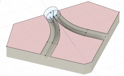
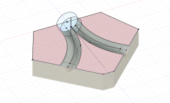
A little experiment with a combiner in Akabak. The idea is to have a circle shaped exit with the same area as the two inputs, treat it as two semicircles, perform loft between input and semicircle, a spline that connects the centers of mass is used as the centerline for the loft bends the loft 45 degrees.
I suppose an ideal result would be that at the endpoint the two semicircles would join with overlapping infinitely thin edges giving the circle shaped exit as the result. I didn't get this result from what I've drawn up in Fusion manually, the channel volumes did have a some intersection before the endpoint, maybe it has to do with the curvature of the spline. (This is where math and coding would come in.)
However that would have to be compromised anyway by thickening that junction so that it's more realistically printable, so as a simplistic workaround the two semicircles are positioned apart at the endpoint by a thin wall amount (0.6mm in this example) and this happens to be enough buffer to prevent intersection of channel volumes. The shape of this exit is two semicircles with a thin rectangle in between, so there's an extra loft (9mm long, arbitrarily) from this to the final circle shape.
The splines are control point splines (NURBS?) with perpendicular constraints to the 45deg walls on the input side and the walls on the output side. The rest (like the walls on the input side, 122mm in this example) is mostly from sizing to be able to fit an actual driver. It would be printed in two pieces like in the picture and bolted together maybe.
The diameter of the inputs is 16mm (like the phase plug exit in the BMS driver) and so the exit diameter is 22.627mm. The sim is with a flat disc diaphragm and the exit is terminated with damping wall impedance. The second FR is sim of a 90mm long 16mm diameter tube.
Attachments
The idea of constant area seems legitimate at first but I think that the longer is this constant-area segment, the more critical will be the area expansion afterwards, which will have to be pretty slow for a smooth overall results. Probably some expansion should be present already within the combiner, and continue to expand smoothly in the following device, i.e. making it one smoothly-expanding system. (And ideally, this should account also for an expansion inside the phase plug.) You can afford a slow expansion as long as the resulting combined throat diameter is still small enough.
- If this really worked, I would try to combine at least three 🙂
- If this really worked, I would try to combine at least three 🙂
Last edited:
I tried ND3T: https://www.at-horns.eu/gen2m.html#nd3tDoes any of these 1.4" drivers with short throats like t520-ND3N can actually play down to 500-600hz range with good results?
It will do 500 Hz with ease, IMO.
Last edited:
In the datasheet of BMS 4555 there's an SPL graph that is quite close to the measured curve on the A520G2 (thin black line overlaid), regarding the behaviour between 6 - 10 kHz, so this is probably the basic behaviour of the driver and could only be "masked". Otherwise both horns seem to be good match (probably better than the horn on which was the 4554 measured in its datasheet).

Last edited:
Right, I only thought of the expansion inside the phase plug and chose ignore it for a start by pretending it's the BMS phase plug which has maybe no expansion.The idea of constant area seems legitimate at first but I think that the longer is this constant-area segment, the more critical will be the area expansion afterwards, which will have to be pretty slow for a smooth overall results. Probably some expansion should be present already within the combiner, and continue to expand smoothly in the following device, i.e. making it one smoothly-expanding system. (And ideally, this should account also for an expansion inside the phase plug.) You can afford a slow expansion as long as the resulting combined throat diameter is still small enough.
- If this really worked, I would try to combine at least three 🙂
The channels are 60.778mm + 30.27mm, probably too long. Maybe the spline could be somewhat shorter. (Set the length of the control segments to be 2x the cross section just based on eyeballing the curvarture.) Changing the wall lengths to 74mm for the smaller 5530ND driver, then the channels are 60.778 mm + 6.27mm long.
Don't know right now how the expansion should look like to match up with given a WG. Something like calculating intermediate loft shapes, scaling them according to the expansion profile, calculating Z coordinates according to the position on the spline, curve fitting NURBS to the expansion profile and shapes could work. The NURBS-Python package could be used for curve/surface fitting and the resulting control cage loaded even into Fusion, could be one way modeling it.
Attachments
Once you start considering such morphing of the cross section, it could make sense to consider also noncircular exit shapes, as you are no longer limited. I would need to look into Ath what are the possibilites to implement something like this. It's not difficult, just tedious. I can imagine a (super)elliptical throat would bring some new possibilities to horn design.
Last edited:
Hi Marcel,
I'm having trouble working out how to use Source.Contours to replicate your throat extension tests here: #13,582. Regardless of zoff, I can't seem to make the waveguide shift from z=0, to start at the end of the duct, as depicted in that post. Rather, the extension protrudes backwards (through the thickened rear surface, borking the sim).
Presumably, I cannot just specify the Source.Contours as per the dome tweet example in the ath user guide, and additional geometry/params are needed to adjoin the sections. What am I missing in my cfg?
Thanks for your help!
; Throat extension duct test
; ST260
R-OSSE = {
R = 130
r0 = 12.7
a0 = 0
a = 39
k = 1.8
r = 0.3
b = 0.3
m = 0.8
q = 3.7
}
Source.Contours = {
zoff -25
point p1 0 0
point p2 0 12.7
line p1 p2 1
line p2 WG0 0
}
Source.Velocity = 2
Mesh.SubdomainSlices =
Mesh.WallThickness = 10
ABEC.SimProfile = 0
ABEC.SimType = 2
ABEC.f1 = 200
ABEC.f2 = 20000
ABEC.NumFrequencies = 40
ABEC.MeshFrequency = 30000
ABEC.Polars:SPL = {
MapAngleRange = 0,180,37
NormAngle = 10
Distance = 10
}
Report = {
Title = "ext duct test 25mm"
Width = 1200
Height = 750
PolarData = SPL
NormAngle = 10
}
Attachments

For a simple conical extension use this instead:
(The problem with Source.Contours is that the outside shell of the waveguide is not automatically extended behind the source and there's probably no easy way around this. It probably wouldn't present a problem in a 3D sim, but apparently it's a problem in the CircSym mode. You would need to move the last two points of the outer profile further back manually in nodes.txt each time.)
BTW, much more advanced means for creating throat extensions are included in the Cults packages for the A*G2 waveguides, including Ath scripts.
Code:
Throat.Ext.Length = 25
Throat.Ext.Angle = 0BTW, much more advanced means for creating throat extensions are included in the Cults packages for the A*G2 waveguides, including Ath scripts.
Last edited:
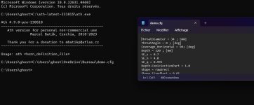
Hello, I come here because I have a problem to use ATH4, even after following the guide I still don't get it...
Well, I can open the program. I have my definition file in .cfg with a test script in it. If I type the name of the file and press "enter", it only opens the file.
I can't figure out what's wrong...
Thank you for your answers
Well, I can open the program. I have my definition file in .cfg with a test script in it. If I type the name of the file and press "enter", it only opens the file.
I can't figure out what's wrong...
Thank you for your answers
Attachments
I found the error, because the CMD directory was not good ( need to be linked to the ath directory). It works now! 😎
View attachment 1382624
Should I be concerned about these holes?
My 3D optimizations aren't going as well as my 2D ones, and unfortunately they don't seem to translate well from 2D to 3D either.
Oh definitely
I've seen this happen to my sims when the shape changes too quickly, especially if you're leveraging the feature in ATH where you can set the waveguide shape arbitrarily.
IE, if you have a round waveguide and you try and make it square, if it changes to fast, you might get holes in the mesh. I'm no expert on this, but I assume it's a combination of the mesh being too coarse and the change in shape is too fast. Easy way to fix it is to just use a slower transition.
Yeah, I think I got that worked out with increasing the resolution.
My script now also changes a0, a, k, s and n on the vertical axis. The interaction of those parameters is going to be interesting.
Now I'm trying for a report png with both horizontal and vertical SPL, but there doesn't seem to be an easy way for this.
Also, the polars.txt only contains the horizontal data and there's no polars_v.txt, so I guess reading the Spectrum_ABEC.txt is next on the todo and then adding matplotlib should be a piece of cake.
And I added Morph.FixedPart and Morph.Rate to the variables as well, as it's not intuitive to me how it affects the shape.
Also, any recommendations on an upgrade to a Ryzen 7 3700X? An EPYC 7532 would be nice, but with a fitting mainboard that's >500€ just for some simulations.
My script now also changes a0, a, k, s and n on the vertical axis. The interaction of those parameters is going to be interesting.
Now I'm trying for a report png with both horizontal and vertical SPL, but there doesn't seem to be an easy way for this.
Also, the polars.txt only contains the horizontal data and there's no polars_v.txt, so I guess reading the Spectrum_ABEC.txt is next on the todo and then adding matplotlib should be a piece of cake.
OSSE = {
r0 = 14.0 ; Initial throat radius [mm].
a0 = 45.5 - 1.3400000000000034*sin(p)^2 ; Initial throat coverage angle [deg].
a = 60.0 - 20.0*sin(p)^2 ; Mouth coverage angle [deg].
k = 4.43 - 0.96*sin(p)^2 ; Flare constant (rate of expansion).
L = 33.8 ; Length of the waveguide [mm].
s = 0.54 - -0.010000000000000009*sin(p)^2 ; Shape exponent for the termination section.
n = 5.07 - 0.5980000000000003*sin(p)^2 ; Curvature control exponent for the termination.
q = 1.0 ; Transition smoothness parameter at termination.
}
_Mesh.ZMapElementSize = 0.1,0.3,0.25,0.85
Mesh.ZMapPoints = 0.3,0.2,0.7,0.9
_Source.Contours = {
dome WG0 22 5 3 -1 3 1
}
Source.Contours = {
zoff 0
point p1 4.9 0 4
point p2 0.75 10.5 0.75
point p3 0 10.5 1
point p4 -0.25 10.75 1
point p5 0 11 1
point p6 1 12 1
point p7 0 13 2
point p8 0 14.5 5
cpoint c1 -15.36 0
cpoint c2 0 10.75
cpoint c3 0 12
arc p1 c1 p2 1
line p2 p3 1
arc p3 c2 p4 1
arc p4 c2 p5 1
arc p5 c3 p6 0.75
arc p6 c3 p7 0.25
line p7 p8 0
}
Morph.TargetShape = 1
Morph.FixedPart = 0.0
Morph.Rate = 2.01
Morph.AllowShrinkage = 1
Morph.TargetWidth = 130
Morph.TargetHeight = 100
Morph.CornerRadius = 5
Source.Velocity = 2 ; axial motion
Mesh.Enclosure = {
Spacing = 30,30,30,30
Depth = 200
EdgeRadius = 30
EdgeType = 1
FrontResolution = 7,7,7,7,
BackResolution = 20,20,20,20
}
Mesh.Quadrants = 1 ; =1 for 1/4 symmetry,
;Mesh.VerticalOffset = 80
Mesh.AngularSegments = 64
Mesh.LengthSegments = 14
Mesh.SubdomainSlices =
Mesh.ThroatResolution = 3
Mesh.MouthResolution = 6
Mesh.InterfaceResolution = 5
Mesh.RearResolution = 20
ABEC.SimType = 2 ; 1 = Infinite Baffle, 2 = Free Standing
ABEC.f1 = 1000 ; [Hz]
ABEC.f2 = 20000 ; [Hz]
ABEC.NumFrequencies = 13
ABEC.MeshFrequency = 1000 ; [Hz]
ABEC.Polars:SPL_H = {
MapAngleRange = 0,90,19
_NormAngle = 10 ; [deg]
Distance = 2 ; [m]
Offset = 99 ; [mm]
_Inclination = 0
}
ABEC.Polars:SPL_V = {
MapAngleRange = 0,90,19
_NormAngle = 10
Distance = 2
Offset = 99 ; [mm]
Inclination = 90
}
Output.STL = 0
Output.ABECProject = 1
Report = {
Title = "ATH report. All praise mabat!"
NormAngle = 10
Width = 1800
Height = 1200
SPL_Range = 50
MaxRadius = 90
PolarData = SPL_H
PolarDataV = SPL_V
}
Also, any recommendations on an upgrade to a Ryzen 7 3700X? An EPYC 7532 would be nice, but with a fitting mainboard that's >500€ just for some simulations.
Last edited:
- Home
- Loudspeakers
- Multi-Way
- Acoustic Horn Design – The Easy Way (Ath4)