I just noticed the default horizontal plane is not the same plane with smoother corner transition.

With Inclination = 90 it looks like this:

Thankfully I'm still far away from having a waveguide where having that extra resolution results in a noticeable difference. 😀
Any hints how to speed up simulations without loosing much 'resolution'?
With Inclination = 90 it looks like this:
Thankfully I'm still far away from having a waveguide where having that extra resolution results in a noticeable difference. 😀
OSSE = {
r0 = 14.0
a0 = 25.01
a = 55.0
k = 35.0
L = 35.0
s = 0.7
n = 4.0
q = 0.996
Mesh.ZMapElementSize = 0.1,0.3,0.25,0.85
Source.Contours = {
dome WG0 22 5 3 -1 4 1
}
Morph.TargetShape = 1
Morph.FixedPart = 0.0
Morph.Rate = 3
Morph.AllowShrinkage = 1
Morph.TargetWidth = 130
Morph.TargetHeight = 130
Morph.CornerRadius = 10
Source.Velocity = 2 ; axial motion
Mesh.ZMapPoints = 0.3,0.2,0.7,0.9
Mesh.Enclosure = {
Spacing = 15,15,15,15
Depth = 150
EdgeRadius = 15
EdgeType = 1
FrontResolution = 8,8,16,16
BackResolution = 24,24,24,24
}
Mesh.Quadrants = 1 ; =1 for 1/4 symmetry,
;Mesh.VerticalOffset = 80
Mesh.AngularSegments = 100
Mesh.LengthSegments = 26
;Mesh.CornerSegments = 4
Mesh.SubdomainSlices =
Mesh.ThroatResolution = 5
Mesh.MouthResolution = 10
Mesh.InterfaceResolution = 8
Mesh.RearResolution = 20
ABEC.SimType = 2 ; 1 = Infinite Baffle, 2 = Free Standing
ABEC.f1 = 1000 ; [Hz]
ABEC.f2 = 20000 ; [Hz]
ABEC.NumFrequencies = 100
ABEC.MeshFrequency = 1000 ; [Hz]
ABEC.Polars:SPL = {
MapAngleRange = 0,90,19
NormAngle = 10 ; [deg]
Distance = 3 ; [m]
Offset = 95 ; [mm]
Inclination = 90
}
Output.STL = 0
Output.ABECProject = 1
Report = {
Title = "ATH report. All praise mabat!"
NormAngle = 10
Width = 1200
Height = 800
SPL_Range = 50
MaxRadius = 90
PolarData = "SPL"
}
[/config]
That's how you defined it in the script. The upper right corner has resolution 8 mm, while the lower right corner has 16 mm. You can change that.I just noticed the default horizontal plane is not the same plane with smoother corner transition.
FrontResolution = <f1,f2,f3,f4>
Front baffle mesh resolution for corners in quadrants 1 - 4, [mm].
Maybe you can decrease the number of Mesh.LengthSegments a bit. That will save you some elements but probably not that much.
A460D + B&C DH450 with a "matched" adapter:

Here it was with the default adapter (the original part of the kit):
I will update the A460D download package.
Here it was with the default adapter (the original part of the kit):
A460D + B&C DH450

A460D + Lavoce DF10.144LK

A460D + Lavoce DF10.144LK

I will update the A460D download package.
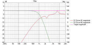
BTW, I'm still chasing down the cause of the on-axis diffraction around 1.4 kHz (or whatever it is), but to no avail. I even tried to simulate various imperfections of the shape but couldn't create anything similar enough. It's strangely narrow-band.

So, two adapters are currently included in the kit:I will update the A460D download package.
0 deg (e.g. DH450, HF1000)
21.7 deg (DFM-2535)
- I was curious about the DH450 and it seems it has indeed no expansion inside the driver. Otherwise it probably wouldn't be so smooth in the midrange.
Last edited:
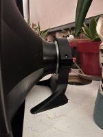
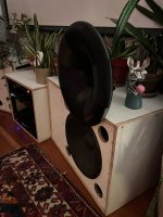
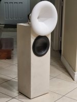
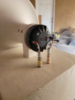
I finished printing the A460D waveguides. Using them with PRV D290PY drivers. Did a quick single measurement tune so I could listen to them and am very impressed! I printed them in ABS and glued them together with acetone. The splines work great for assembly and the driver adapter is really clever. I whipped up some mounts that hold things up from the driver. Woofers are 15" - McCauley 1560B. Looking forward to trying out some other drivers.
Attachments

BTW, there are already four adapters included in the kit: 0 / 12 / 21.7 / 31 deg.
You can choose the one which suits your driver best. If in doubt, this can be easily tried, as it's only a simple part replacement.
You can choose the one which suits your driver best. If in doubt, this can be easily tried, as it's only a simple part replacement.
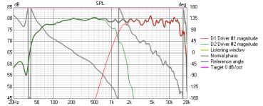
Attached is the raw response - I was getting natural roll off starting at 1300hz so didn't feel I could cross over as low as I would like. I'll have to try the 0 and 12 deg. adapters to see how it responds. The PRV D290PY is a DE250 clone, so if they copied the exit angle it would be 14.6 deg.Nice to see them finished in such a clean way, thanks for sharing. The WG mount looks great. The crossover point would seem a little bit high, but I don't know the drivers used.
Attachments
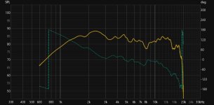
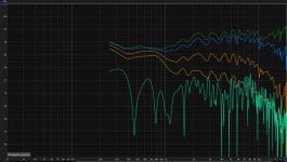
Just wanted to share another build from one of your waveguides. I printed the EXAR400 as a single piece and paired it with a LaVoce DF10.142LK. The woofer is a Dayton SIG270 10" in a sealed box. The measurements are 0, 15, 30, 45, and 90 deg with 4ms gating on one and psychoacoustic smoothing on the other. I put a 10 ohm resistor in series with the CD. I'm loving the sound!
Attachments

The appearance is greatly pleasing, congrats.
As for the performance, I think it would deserve a better measurement (but of course I understand the difficulty). From what can be read it seems that the crosover is around 1 kHz, probably somewhere just above that, as that's where the directivity noticeably changes. Maybe with a different HF driver it would be possible to shift the Xover lower and utilize the more gradual DI slope of the WG alone. At least that was the original idea. But I believe it sounds good already. Nice work indeed. Would be interesting to see the raw HF driver alone.
The measurement "with 4ms gating" looks pretty scary and I believe it's not the actual performance of the device, but hard to say what's wrong. Looks like a strong reflection or something. The smoothed one is the same, only smoothed.
In a single piece?? I would love to know more about that.I printed the EXAR400 as a single piece
Last edited:
I'm honestly an idiot when I comes to taking measurements and the room is totally reflective. I crossed it at 1.2kHz. The electronics are still sitting outside the second enclosure so I might play around with tuning it in a bit more.
As far as it being a single piece, I reassembled the pedals and base in freecad from you STL files and then printed it mouth down on a 400x400mm printer.
As far as it being a single piece, I reassembled the pedals and base in freecad from you STL files and then printed it mouth down on a 400x400mm printer.
Attachments

Just got suspicious of my assembly and gave the horn a shake. Turns out one of the screws sound a little loose, I'll have to tear it apart and remeasure it
Last edited:
Trevor, is that the anycubic Chiron? I've got one but could never get decent results. Any tips for decent prints?
It's an Anycubic Kobra Max. I was printing with Elegoo Rapid PETG on a 0.6mm nozzle. I forget the rest of the settings used, but i want to say it had a 70C bed and 230C nozzle. The extruder head is modified for direct drive rather than the stock bowden. I'm not too sure about the details of that modification, as I bought it used with the DD installed by the previous owner
Hi Mabat, I've been starting to look through this thread recently as I look at building out my first horn system.
I wanted to ask, is this 1.5" adapter for the 4015 series available? I couldn't see it on your websites, the only 1.5" was the JBL which I think has different mounting spacing. If it is, I'd be very keen to give it all a go. Cheers!
- Home
- Loudspeakers
- Multi-Way
- Acoustic Horn Design – The Easy Way (Ath4)