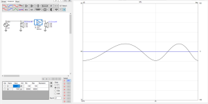
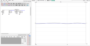
I am not so happy with what became visible in the results of the high definition rendering of a 25.4 mm throat device. With EQ, however, In Room Response might become acceptable, concerning the top octave.
1 kHz LR24, 360 mm vertical c-c spacing, some EQ.
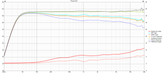
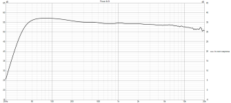
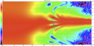

VACS
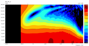
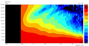
Cardioid metrics
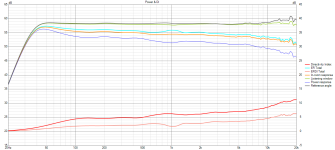
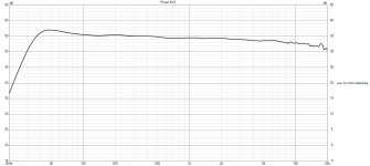
1 kHz LR24, 360 mm vertical c-c spacing, some EQ.


Code:
R-OSSE = {
  R = 160     - 40*sin(p)^2
  r0 = 12.7
  a0 = 10.85
  a = 59     - 14*trwu(0.4, 0.8, 2, p)*sin(p)
  k = 0.3     + 3.5*trwu(0.4363, 0.6, 5, p)*sin(p)
  r = 0.18     - 0.1*cos(p)^2 + 0.02*sin(p)^2
  b = 0.2     + 1.3*cos(p)^2
  m = 0.78
  q = 4     + 4*trwu(0.4363, 0.6, 5, p)*sin(p)^2
}


Mesh.LengthSegments = 48
Mesh.AngularSegments = 120
Mesh.SubdomainSlices =
Mesh.WallThickness = 6
Mesh.ThroatResolution = 5
Mesh.MouthResolution = 7
Mesh.RearResolution = 25
;Mesh.ZMapPoints = 0.5,0.1,0.76,0.733

Mesh.SubdomainSlices = 35
Mesh.InterfaceOffset = 25
Mesh.InterfaceDraw = 0

ABEC.MeshFrequency = 1000
ABEC.NumFrequencies = 100
ABEC.Abscissa = 1
ABEC.SimType = 2
ABEC.f1 = 500
ABEC.f2 = 20000
VACS


Cardioid metrics


Hah, yeah it is, I bet I cannot implement it to this accuracy. But it's also an exersice to understand these devices a bit better so why not 🙂It's a bit absurd already, but here's my current benchmark. Looking forward to your results 🙂
For example here is one from few days ago that converged with two rounds with simple optimization attempt, and doesn't seem to get any better with small adjustments hinting something is fundamentally wrong with this particular curve. While it's pretty good, it's not possible to get rid of edge diffraction artifacts as your G2 does.
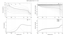
It's also R=230 to keep the data comparable. All attempts for wider pattern than G2, so far, have similar issues, diffraction related ripple showing up either on the 6dB line on the polar map, around 1kHz like in yours, and / or it's also around 2-3kHz in listening window visible with the 1dB line, and these two are very persistent hinting it's a fundamental issue with the devices I've come up with. There is either or both at some degree, and these go more or less away with tmax backside, telling it's just edge diffraction. Conveniently delay to make the interference is about the length of the curve.
To get rid of these, less sound need to go to edge and be projected away to avoid having to implement the tmax backside. This seems to happen with deeper device as is 460G2, it really doesn't have any sign of these. I'm not sure if anything less deep (compared to diameter) can achieve this. The above device is only ~12cm deep if I remember, and I bet your example on previous post is deeper than this as it's cleaner. Is it, something around 15cm deep perhaps?🙂
ps. +/-1dB ripple means secondary sound is roughly 40dB down of the direct sound, and delayed with the profile length so closing in 1ms with such large devices. Perhaps it's nothing audible, I'd just obses to get it disappear just because 😀
Last edited:
As for a wider pattern, I already have that one as well (not available yet) -
(Just to show what I ended up with. It doesn't have to be big but it's still full of diffraction by your criteria.)
(Just to show what I ended up with. It doesn't have to be big but it's still full of diffraction by your criteria.)
I'm working on a small, complete loudspeaker kit. This is the waveguide (28cm), to be used togeter with a passive cardioid midrange -
This is measured with the DF10.171K, it will probably stay.

Polar map normalized @ 10 deg.
The raw polars (0 - 80 / 10):

The original simulation:

This is measured with the DF10.171K, it will probably stay.
Polar map normalized @ 10 deg.
The raw polars (0 - 80 / 10):
The original simulation:
Last edited:
Yeah I think it's impossible to have wide ~constant directivity "horn looking" device (shallow depth compared to diameter) and get rid of all the edge diffraction ripple because more and more sound gets to the edge to diffract the wider the pattern is. Your example is quite good already. If you want to get completely rid of it make the backside enclosed, basically make a device that approaches shape of a ~sphere but with tmax. This is a possibility yes, it's just more work to manufacture and perhaps not so appealing visually as "horn" looking device. G2 are ideal in this sense, about no sound reaches the edge, ~all is projected forward by the profile. Diffraction from the edge is more than 40dB down, because not showing up in the standard graphs. Whether it is audible or not is another question 😀
Last edited:
Last edited:
Maybe someone could model a few of the normal build "misstakes" and show what the impact is? 🙂
//
//
It depends, completely different parameters could give "similar ripple", and if you just move one parameter few % it could change this small ripple quite much, but not cure it. Bigger changes would make bigger difference, and to maintain "smoothness" something else needs to change as well to compensate. On some settings one variable might do absolutely nothing, while on another settings it would be quite sensitive and so on. Basically maintain smooth curvature without sudden changes is the basic rule, by juggling all the variables as necessary.
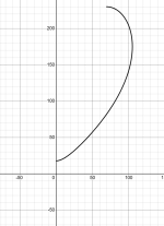
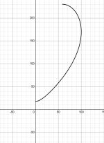
Here is one example, one variable (b) changes about 25% between them. As you see change is mostly on the end of the curve, so change in frequency response is at the low end, where wavelength is similar to size as the feature that changed.
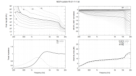
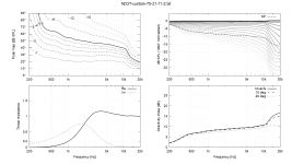
edit.
Here GIF animation from another set, where two variables are permutated other staying the same. One moves with ~10% steps while the other with ~3% steps.
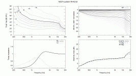
Here is one example, one variable (b) changes about 25% between them. As you see change is mostly on the end of the curve, so change in frequency response is at the low end, where wavelength is similar to size as the feature that changed.


edit.
Here GIF animation from another set, where two variables are permutated other staying the same. One moves with ~10% steps while the other with ~3% steps.

Last edited:
Thanks! So thats about a 2mm change that gave say 0,5dB at 0,8k but no big wide impa otherwise. For this case....
//
//
If you look at tip of the profile it moves about 1cm back, the scale is 10mm per line on the graph. At point in the curvature the change is less in this case, so not much change in throat for example, so highs do not change mucho at all. Rouhly put, curve at the throat affects highs and curve at mouth the lows, and when ever sound diffracts due to too much change in curvature, a delayed and inverted copy of sound launches backwards. This happens at the mouth edge usually, but could happen at any point inside the device as well when ever there is sudden change in curvature. Studying interference ripple you can read delay between interfering sounds from the ripple period. Bandwidth of secondary sound is seen for what bandwidth the ripple happens, basically amplitude of interference ripple shows how loud secondary sound is at any frequency. Using bit of logic it's relatively easy to "see" where the diffraction happens, and why. The why is easy, no need to see it, it's just change in curvature, which you can get with derivative, which you can plot in Desmos for example.
edit. mabat shared Desmos graph to show change (derivative), and how fast it changes (2nd derivative)
edit. mabat shared Desmos graph to show change (derivative), and how fast it changes (2nd derivative)
In the following Desmos graph blue is the curvature and red its derivative (rate of change), R-OSSE profile used:
https://www.desmos.com/calculator/hbsq4xght6

There's a room for an analysis... 🙂
https://www.desmos.com/calculator/hbsq4xght6
There's a room for an analysis... 🙂
Last edited:
Example, if you make ~circular arc the curvature doesn't change almost at all and there is no diffraction, except at the very end it would as the profile doesn't exctend all the way around.
https://www.desmos.com/calculator/fpmhtbdupl
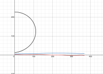
If you do something weird like below, you'd have diffraction launch where the red line goes bonkers. This is around ~21cm mark along the curvature, so expect ripple in the response about ~21cm =~1600Hz interval, pretty much for the whole bandwidth starting from null around the ~1600Hz, see attached VituixCAD sim "emulating" inverted diffraction backwave with 21cm delay.
https://www.desmos.com/calculator/jv5nsljvmb
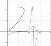
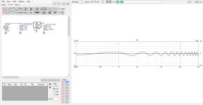
For example here is just some random settings I just dialed, which has smooth curve until the mouth edge where it inevitably diffracts:
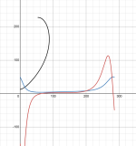
I suspect the last has relatively nice directivity in general sense, except likely diffraction ripple the whole bandwidth because it's a shallow device and edge terminates rapidly. Well, didn't try to simulate so just a guess. Anyway, this is the process I do hand cranking this stuff. I'd look at how this one simulates, and adjust accordingly. If top is poo, I'd change stuff that changes curvature near throat, and make sure the overall curvature ends up nice by adjusting what ever parameters necessary looking at the red and blue lines. If there is diffraction ripple, I'd work on the mouth termination more, trying to reduce both red and blue peak and push it further out by making the device deeper, unless it needs to have wide top, and so on 😀 Hand crank few hundred and you'll get touch for it 😀
https://www.desmos.com/calculator/fpmhtbdupl

If you do something weird like below, you'd have diffraction launch where the red line goes bonkers. This is around ~21cm mark along the curvature, so expect ripple in the response about ~21cm =~1600Hz interval, pretty much for the whole bandwidth starting from null around the ~1600Hz, see attached VituixCAD sim "emulating" inverted diffraction backwave with 21cm delay.
https://www.desmos.com/calculator/jv5nsljvmb


For example here is just some random settings I just dialed, which has smooth curve until the mouth edge where it inevitably diffracts:

I suspect the last has relatively nice directivity in general sense, except likely diffraction ripple the whole bandwidth because it's a shallow device and edge terminates rapidly. Well, didn't try to simulate so just a guess. Anyway, this is the process I do hand cranking this stuff. I'd look at how this one simulates, and adjust accordingly. If top is poo, I'd change stuff that changes curvature near throat, and make sure the overall curvature ends up nice by adjusting what ever parameters necessary looking at the red and blue lines. If there is diffraction ripple, I'd work on the mouth termination more, trying to reduce both red and blue peak and push it further out by making the device deeper, unless it needs to have wide top, and so on 😀 Hand crank few hundred and you'll get touch for it 😀
Last edited:
In fact it's the curvature and the rate of change of curvature (its 1st derivative) along the curve, but not linearly.edit. mabat shared Desmos graph to show change (derivative), and how fast it changes (2nd derivative)
BTW, I suspect that the R-OSSE parameter 'b' is redundant (i.e. could be ommited altogether / set to zero), but it's so long ago when I devised the formula that I completely lost the trace and can't find any notes. So I don't have a clue anymore why it's there.... 🙂
You and your fancy round overs. 😀
Out of curiousity: Is it possible to add a roundover and an enclosure line to SimProfile = 0, circular symmetry mode or is this only possible in 3D?
Out of curiousity: Is it possible to add a roundover and an enclosure line to SimProfile = 0, circular symmetry mode or is this only possible in 3D?
For axial symmetry there's the "RearShape":
So the promised user-defined back side as a cubic Bezier curve:
Mesh.RearShape = 5 ; closed back
Mesh.RearCubic = -60,2,50,-80,5 ; [mm]
https://at-horns.eu/ext/ath-4.9.0-pre-230109-2.zip


You will lose LF directivity this way. To regain, you will probably need to increase the overall size. That's the drawback I see.
Mesh.RearShape = 5 ; closed back
Mesh.RearCubic = -60,2,50,-80,5 ; [mm]
https://at-horns.eu/ext/ath-4.9.0-pre-230109-2.zip
You will lose LF directivity this way. To regain, you will probably need to increase the overall size. That's the drawback I see.
This either doesn't work for OSSE or in the current version of ath. The download link is a 404 unfortunately.For axial symmetry there's the "RearShape":
So the promised user-defined back side as a cubic Bezier curve:
Mesh.RearShape = 5 ; closed back
Mesh.RearCubic = -60,2,50,-80,5 ; [mm]
https://at-horns.eu/ext/ath-4.9.0-pre-230109-2.zip


You will lose LF directivity this way. To regain, you will probably need to increase the overall size. That's the drawback I see.
If not you could implement it yourself, take last coordinates, the end of the line, and make custom bezier curve from that as enclosed back. Old discussion here https://www.diyaudio.com/community/...-design-the-easy-way-ath4.338806/post-7228138
I found a PHP script I used back then to make the whole curve, R-OSSE + bezier back side starting from last coordinates R-OSSE returned. Then in ath configuration file use Profile to define this custom profile, and the rest of the process is normal I think, ath.exe creates ABEC project with this custom profile instead, can't remember how it exactly worked. This is option if Mabat doesn't have the backside readymade for OSSE
I found a PHP script I used back then to make the whole curve, R-OSSE + bezier back side starting from last coordinates R-OSSE returned. Then in ath configuration file use Profile to define this custom profile, and the rest of the process is normal I think, ath.exe creates ABEC project with this custom profile instead, can't remember how it exactly worked. This is option if Mabat doesn't have the backside readymade for OSSE
- Home
- Loudspeakers
- Multi-Way
- Acoustic Horn Design – The Easy Way (Ath4)
