It's actually made of those harmonics. And if you cut them away (pass through an LP filter), you change that waveform and it will lose its transient character - there will simply be a slow onset and fadeaway instead. Nothing I would call a transient anymore, but I agree this is all pretty vague.The thing is that the start up and shut down transient of a steady state frequency like above creates harmonics [...]
(If you could cut off everything except one single frequency, you would get an infinitely long steady state response (a sine) - there's not anything else that a single frequency can represent in time. So it's not even possible.)
Last edited:
This is just an illustration that it doesn't really matter what exact point is chosen as a reference. You simply choose one, somewhere in the center of the construction, most obviously, and then simply measure far enough from that point. If there are "rules" that are tied to a "baffle", they are superfluous and only obfuscating the real issues, IMO.
Fully agree with this.
As long as we can use a measurement distance that approximates listening distance, and is also distant enough to be in the acoustic far-field,
we can use whatever physical driver arrangement offset with fixed delays, and be more ok than not.
Biggest problems with doing that, I've found are:
it's harder to make good measurements that satisfy both those distance requirements than it appears, due of course to reflections.
and trying to rotating a speakers' baffle (or horn mouth in the case of my large MEHs) centered on a turntable around is near impossible. Half of the uncovered turntable reflects/diffracts into the measurement.
Have had to use an overhead rotating mic boom to assess rotations around horn mouth. Need a moving-mic Kippel machine lol.
I created a simple script to automate creating configs with variable parameters, running ABEC with some pixel detection, creating the reports and then moving those reports to an output folder.
I'd like to use it to simulate waveguides in an enclosure of fixed size, so the morph feature would be necessary. Is it possible to have ath return the diameter of the the waveguide if it was done in circular mode, so the script could compare that to the morph target size and omit the simulations where the difference is too big?
If you want to try my script:
-extract in the ath.exe folder
-edit the config.ini with your file paths
-run _pixelpos.py to set up the coordinates of the pixels to check for ABEC progess
-edit the base_template.txt to your liking. Use double {{}}, as single {} are for the variable parameters
-edit params.ini
-run mach_durch.py (forgot to rename that)
-report bugs to ChatGPT
It's a very simple script and does not have very good error handling, yet. But it ran on my machine for >8hours without problem.
Todo: Read the results and find a way to sort the results by smoothness of a mix of lines.
Attachments
The thing is that the start up and shut down transient of a steady state frequency like above creates harmonics or as you call it, wide band content.
It's not harmonics, it's wide band content. The convolution theorem states that convolution in one domain (e.g., time domain) equals point-wise multiplication in the other domain (e.g. frequency domain). The signal you show is a point wise multiplication of an infinitely long single frequency sine wave with a rectangular function.
The Fourier transform of an infinitely long single frequency sine wave is a 'spike' (/delta function) at the frequency of the sine wave. The fourier transforms of a rectangular function is the sinc function. Convoluting these two gives a sinc function centered around the sine frequency with a width (inversely) dependent on the width of the rectangular function (the sine duration, so to say). This is a widened band iso the spike, but no harmonics of the sine wave frequency appear.
But it isn't particularly constant horizontally either, is it.
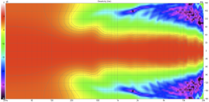
I don't want to derange this thread on transitive forms of existence, but I thought I would see what directivity the BMS 4554 minimum aperture (16 mm) allows.
Here is the sims for a simple two-way (10-inch woofer).
1) VACS

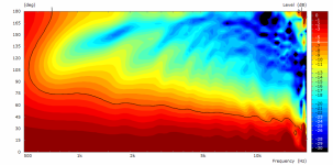
2) VCad
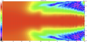
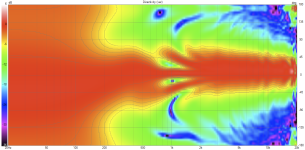
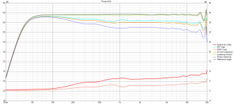
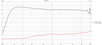
And for the sake of it, what how this waveguide simulates in a 3-way cardioid speaker:
1) VCad
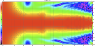
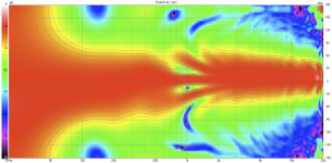
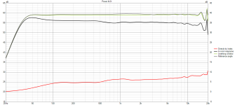
Pretty constant, no?
[edit] frontal view for aesthetical considerations:
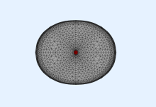
This is the waveguide definition for the asymmetrical freestanding device from the post cited below:
Parameter r0 changed
R-OSSE = {
R = 160 - 33*sin(p)^2
r0 = 8
a0 = 10.85
a = 60 -18*sin(p)^2
k = 0.4 + 2.5*sin(p)^2
r = 0.18 - 0.07*cos(p)^2 + 0.05*sin(p)^2
b = 1.2 + 0.2*cos(p)^2 - 0.5*sin(p)^2
m = 0.8 + 0.1*sin(p)^2
q = 5 - 1*sin(p)^2 + 1*cos(p)^2
}
Last edited:
It's actually made of those harmonics. And if you cut them away (pass through an LP filter), you change that waveform and it will lose its transient character - there will simply be a slow onset and fadeaway instead. Nothing I would call a transient anymore, but I agree this is all pretty vague.
(If you could cut off everything except one single frequency, you would get an infinitely long steady state response (a sine) - there's not anything else that a single frequency can represent in time. So it's not even possible.)
Wavelets seem to be a good 'single frequency' transient.
One type called a Morlet wavelet appear to be used in medical tests, as there are many youtubes on it (and understanding Fourier in general)
The Morlet is a n-cycle sine of a given frequency multiplied by a Gaussian distribution.
So a Morlet (or cosine or whatever window wavelet ) doesn't have a very strong abrupt start/stop, with the accompanying wide bandwidth spectrum abrupt brings.
from:
I was led to Morlet wavelets because they are the wavelets of choice in a measurement program I've been using.
Here is an acoustic capture of a 50Hz one from my sub.
The time domain response is essentially a scope capture, with its mathematically derived frequency response below.
Sounds like 'bump" with your hand over your mouth 🙂
Sure, and that's precisely the transient response where the original transient is almost gone.
Quick and dirty and non-optimized attempt with a more radical vertical constraint. For the following values:
1) VACS
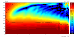
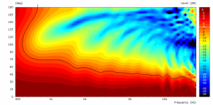
2) VCad (conventional / cardioid)
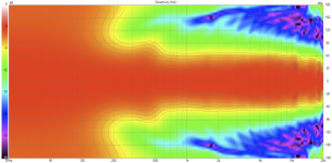
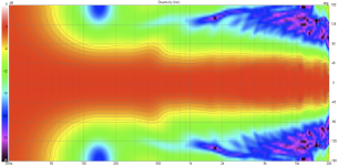
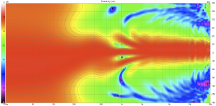
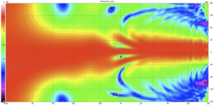
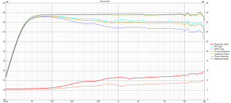
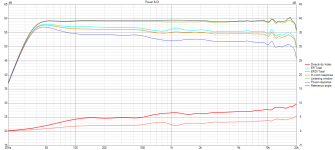
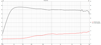
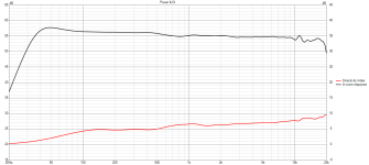
Device profile:
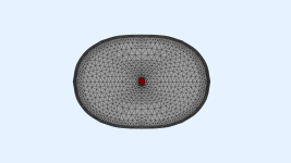

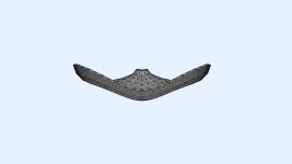
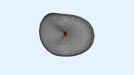
Code:
R-OSSE = {
  R = 160     - 50*sin(p)^2
  r0 = 8
  a0 = 10.85
  a = 60     -18*sin(p)^2
  k = 0.4     + 2.5*sin(p)^2
  r = 0.18     - 0.07*cos(p)^2 + 0.05*sin(p)^2
  b = 1.2     + 0.2*cos(p)^2 - 0.8*sin(p)^2
  m = 0.8     ;- 0.05*sin(p)^2
  q = 5 + 1*cos(p)^2 + 3*sin(p)^2
}
1) VACS


2) VCad (conventional / cardioid)


Device profile:


If you can stand the shape, why not, the data look good indeed. With that small throat you can do these things.
I'm only not sure it will allow a crossover around 1 kHz, that would need to be checked. It may be more like 1.5 - 2k.


I'm only not sure it will allow a crossover around 1 kHz, that would need to be checked. It may be more like 1.5 - 2k.
Last edited:
Smaller 1-inch BMS 4550 looks good:
https://www.justdiyit.com/grand-comparatif-de-compressions-1-pouce/5/
https://www.justdiyit.com/grand-comparatif-de-compressions-1-pouce/5/
What do you mean by original transient? And how is it gone?Sure, and that's precisely the transient response where the original transient is almost gone.
Sorry, no idea what you mean...
Hey, maybe this helps......to precisely match a transient stimulus to it's response, here's a 60Hz 2.5 cycle wavelet.
Yellow is REW's electrical output. Blue is microphone capture.
(Yellow is trigger, the approx 90ms mic delay is from FIR filter on sub.)
That wavelet burst is definitely a "transient" imo.
A transient with little energy away from its 60Hz frequency.....No?
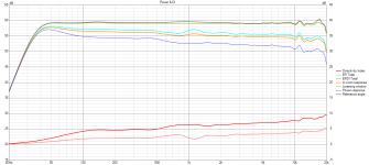
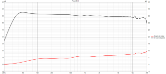
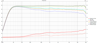
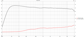
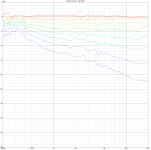
Some measurements of a 340mm prototype waveguide with the BMS 5530ND. Note that the distance at which I measured is too close in this case (roughly 0.5m from horn mouth) and my microphone stand is not ideal. Nonetheless the results look promising:
Unfortunately it does seem the short cylindrical throat introduces some issues in the frequency response. I compared two different throat pieces (similar to what Mabat has shown earlier in this thread), and compared the on-axis frequency response of the two roughly 10cm away from the horn mouth. Orange is the cylindrical piece, red is a smoother shape (no directivity measurements of this one yet):
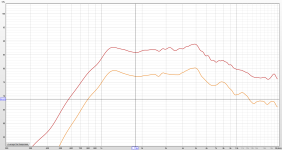

Unfortunately it does seem the short cylindrical throat introduces some issues in the frequency response. I compared two different throat pieces (similar to what Mabat has shown earlier in this thread), and compared the on-axis frequency response of the two roughly 10cm away from the horn mouth. Orange is the cylindrical piece, red is a smoother shape (no directivity measurements of this one yet):

The physical baffle itself is irrelevant, a naked driver should be rotated at the front frame at the same place as the baffle would be if there is one. By problematic I meant a construction with multiple drivers firing in different directions and planes requiring some thought on how to measure in a way that is consistent with what Vituix expects.What problem? I can imagine a free standing waveguide with basically naked woofer and this would be a loudspeaker like any other. This is just an illustration that it doesn't really matter what exact point is chosen as a reference. You simply choose one, somewhere in the center of the construction, most obviously, and then simply measure far enough from that point. If there are "rules" that are tied to a "baffle", they are superfluous and only obfuscating the real issues, IMO.
The point is that when taking measurements to use with Vituix for design work you should not just pick a point in the centre of the construction but follow the measurement instructions included with the program. This is not the same as measuring a complete speaker for display in any basic measuring software.
The context was in relation to using Vituix specifically to measure and design a speaker. All your measurements and displays recently come from SMAART. In that context I would also agree with you but Vituix wants something different to work as designed.Fully agree with this.
The narrow spectral content means that it has almost no transient part (which is the point of a wavelet). How long would the Gaussian window used to create the wavelet need to be so you wouldn't call it transient anymore?That wavelet burst is definitely a "transient" imo.
A transient with little energy away from its 60Hz frequency.....No?
I refuse to call something transient just because it has a beginning and an end 🙂
But I think there's really not much more to this, mostly semantics I guess.
Yeah, the red one seems already close to what's available as the best case for that geometry. It really needs to be made as smooth as possible within the existing throat exit boundaries. Even if it meant some slight narrowing in the top octave, IMO.Orange is the cylindrical piece, red is a smoother shape
In principle this can be EQed but a lot of assumptions are being made and it's surely best to eliminate the need as much as possible.
- Home
- Loudspeakers
- Multi-Way
- Acoustic Horn Design – The Easy Way (Ath4)
