I assume the shape could look different if the tools where able to create it. What's needed is treating the vertical and horizontal sections more independent from one another in the design stage, and blend them with the mesh for smooth transitions in a second step. So to allow to combine two optimized profiles. The result probalby looks like a mixture of a biradial horn, that is terminated the ath way, and the JBL progressive transition waveguides.I couldn't live with that shape 🙂
But it isn't particularly constant horizontally either, is it.
In my case, yes. With your class of narrow devices, especially when the insert-approach is applied, that was demonstrated with the BMS annular diaphragms, it should be much more constant. This is for a 140 degrees device and no compression driver can keep up with this wide of a dispersion in the top octave. I assume it is not detrimental to the sound, though.
If you're after more wide than constant, why bother making the shape so complicated? A good dome tweeter in a round shallow waveguide should fit. It doesn't have to be the T34A if you don't insist on the constant directivity all the way up. But I may be missing something.
- I can try again something along these lines, i.e. a constant H + narrowing V, but it would be rectangular 🙂
- I can try again something along these lines, i.e. a constant H + narrowing V, but it would be rectangular 🙂
Could be. But also, constraining the vertical angles is required for SP. I mean to remember this wasn't all to simple with the domes.If you're after more wide than constant, why bother making the shape so complicated?
I think oval looks very nice for this class of devices. @aragorus showed one on insta a while back that I quite liked as a form principle:... but it would be rectangular 🙂

Last edited:

Hi, I think it should, thats what the coordinate system is for. I thought it should not exactly with deep devices, but I posted both rotation axis processed this way to represent each other, if you look at last eight images of #16044 it seems so. One of the images has error in text, but the settings are correct. IamJF spotted some error, but it's not clear what that was, perhaps the same.Are you sure this post processing delivers the same result as a measurement with correct rotational axis?
If you have time and interest, please try it out. VCAD project including data attached in post #16051.
Last edited:
Hmm, now that am thinking, the data might be wrong from vacs, if impulse from both throat and mouth rotating 0 axis at 2m arrives at same time, the data does not represent what a dual channel measurement would, right? With 2m mic distance from rotation axis, the mouth rotation should have device depth extra path length at 0 axis. I need to check this later when I am back at the computer.
My memory is draining apparently, searching VACS and phase returns million posts from this very thread, for example this one:
Here's a recap regarding phase data:
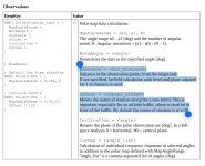
- If you specify Distance in ABEC.Polars, FRs are simply calculated at that distance from the origin and VACS phases include all the propagation delays (may seem "weird" due to wrapping but they are correct). Ath currently removes the delay corresponding to this distance automatically in the FRD export function. This is the recommended way how to obtain the data for a crossover simulation. Don't use any PhaseComp unless you know what you're doing.
- If you don't specify Distance in ABEC.Polars, ABEC...
Transients exist at all parts of the spectrum. Funny thing is, even though the amplitude distortion beginning at the start up transient has to last longer for it to be easily perceived, the act of starting or stopping a waveform of an frequency generates harmonics.And there are no "LF transients", that's all MF/HF stuff.
I agree, and I think this the same thing that happens in common places in nature. The ambient hf ringing of a gun shot, possibly.The HF reflections are certaily more favourable, almost universally perceived as beneficial if delayed enough
If you pass a signal containing "transients" through a low-pass filter, all those transients are simply lost. You can easily try it yourself, after all. Believe me, LF transients are nonsense. You need a wide bandwidth to have transients, that's just how it works.
My memory is draining apparently, searching VACS and phase returns million posts from this very thread ...
This post contains the solution. Notice the linked post and discussion.
The truth is that I mentioned all of this at the moment I introduced the functionality 🙂However, after mabat had indicated that entering PhaseComp in the section FRD export was required
"You have to set an explicit distance for the polars if you want to export them. This will be also the default delay compensation (which you can manually adjust with the PhaseComp value, that will be added to the Distance value)."
https://www.diyaudio.com/community/...-design-the-easy-way-ath4.338806/post-6996527
- Obviously, if you normalize the data...
You want to define distance, phasecomp and offset in the observation section for a controlled measuring script.
Attachments
Does this invoke the 1-1.2x spacing rule of thumb, for which, as I recall, a further rule is that woofer and tweeter should have wide vertical radiation at crossover frequency? But personally I think I'd rather have an asymmetric WG that is tall, rather than wide, so with narrower radiation vertically, and wider horizontally. In this case wider verticals will be found at a lower crossover point, but I think that's always desirable, like generally 700Hz would be just better target than 1200Hz, if the tweeter can keep up. If the WG is "too wide" horizontally at 700Hz, not sure if that can come up, the woofer could be tuned to match it by adding a slot in front.One more aspect for "ideal" waveguide: I posted an example on another thread how matching DI of waveguide and woofer makes bump in system DI. This could be adjusted with c-c but also by making waveguide vertical directivity collapse bit earlier than the horizontal, which means asymmetric waveguide.
Hi, yeah you can easily play with c-c in VituixCAD and choose what you think works better for your application. Crossover slopes also matter. I think point of that rule is that it might be possible to have smoother DI by increasing the c-c, instead of trying to squeeze it like trend has been. I think that for relatively short listening distance hump in DI is not that important as wide main lobe so here you could try and squeeze the sources as close as possible, while listening further out listening height is varies less in terms of angle so main lobe could perhaps be narrower and DI smoother by increasing c-c. It's just one variable in a system design.
My personal opinion is that if you care about listening height, that it needs to be good both sitting and standing, it's better go for a line array or proper point source to ensure it is. And when it's not, optimize the system for any things that seem important and let this c-c stuff float with them. I do not know which situations would be especially better on either, as I haven't done any AB testing and don't know all situations and speakers. So, this is just my reasoning based on hobbyist experiense.
The wide/narrow asymmetric waveguide thing is bit unintuitive. Assuming both the vertical and horizontal profile end at the same plane, like on to a baffle, it means the narrower axis has wider response on long wavelength but narrower on short wavelegth, than the other axis. if you turn the waveguide so that it's tall and narrow, it will have highs wider on vertical axis and lows wider on horizontal axis. Ratio of the dimensions affect how much of the bandwidth the patter is flipped like this. It makes sense to lose directivity on vertical in order to fix vertical response to get net positive though. You certainly could use it tall and anrrow as well if you fidn it useful! What ever makes the directivity collapse and DI match a bit worse, reduces destructive interference and smoothens total DI a bit, same idea as with the c-c adjustment.
Also I'm not 100% certain lower crossover is always better, it's the other variable with c-c that affects lobing, but it's also about distortion and driver sizes and physical size of things so basically it's core of whole system design, after all everything should be to provide perception, so optimize what is better for that. These technical details aren't important on them selves, only in context of listener(s) enjoying system that suits well. So, perhaps the low crossover is important. My general perspective is that any single thing is not important, but multiple things aligned is 🙂 In practice this is just understanding what is required from the system to get a perception, with all other possible constrains like budget, size and looks. It could have low or high xo, low or high c-c, waveguide or no waveguide in a typical meaning of it, and so on, what ever suits. A good system design, with what ever details.
Last edited:
Assuming both the vertical and horizontal profile end at the same plane, like on to a baffle, it means the narrower axis has wider response on long wavelength but narrower on short wavelegth, than the other axis.
Sometimes, intuition, the non-discursive truth that is given, is not enough. The assumption is the opposite, that the vertical walls are longer and, in the case of a free standing device, will not end at the same plane as the horizontal walls. The pattern thus does not collapse, but narrows in a controlled and continuous way, as in my example.
Yeah I saw your post and added the assumption to include your example without making the post ever longer, because it's multihour post to gather illustrations this subject deserves 🙂
Your exanple in post #16036 is nice compromise, without obvious collapse in pattern, but it also has a patternflip about at 1kHz, below which vertical coverage is wider than horizontal, and above that vertical is narrower than horizontal, which is definition for pattern flip as I understand it. It's mainly due to the mouth face is not as high as wide, but also diffraction affects both axis bit differently because the device is not axisymmetric. But this is academic detail only and practice it likely works just fine, maybe better than fine if you cross bit below patternflip as it maintains good horizontal pattern while the vertical "collapses" as woofer narrows making the DI hump at xo bit less.
It seems to be possible to maintain narrower response on the physically wider axis to lower frequency also with diffraction all the way around the device, in addition to wider front face. Another way to combat patternflip for asymmetric pattern is with a "diffraction slot", where mouth face can be symmetric and at same plane, but the throat starts to expand earlier on one axis to get the narrower coverage.
Both cases, diffraction slot or protruding mouth inevitably lead to a bit different diffraction effects as well, even though the mouth face was symmetric. Relatively small ratio of nominal coverages go fine, but the higher it gets the higher frequency the patternflip. Perhaps combination of both mild diffraction slot and symmetric face with bit different horizontal and vertical profiles could get bit higher ratio. Highly asymmetric pattern can be achieved with an array.
Last edited:
Yeah, pas it through a low pass and screen out the mid and hf transients I'm sure. it screens out mid and hf steady state signal too....If you pass a signal containing "transients" through a low-pass filter, all those transients are simply lost. You can easily try it yourself, after all. Believe me, LF transients are nonsense. You need a wide bandwidth to have transients, that's just how it works.
Impulse - A very short, transient, acoustical (or electrical) signal. There's no requirement for a wide bandwidth, its just: a temporary oscillation
If you had only one frequency, it would be nothing but steady state. To make any signal shorter than that, you need a wider band of frequencies. The shorter the "transient", whatever it is, the wider bandwidth it actually represents. Pass it through a narrow-band filter and see what you get. Is any temporary oscillation a transient? I don't know, to me it's something different.
How did we even get here?🙂
How did we even get here?🙂
Last edited:
Hi,
solution for my issue with recent sims was that VACS normalized responses had unwind all the constant delay out up to the impulse by some automatic thing, which removed any differences of acoustic centers in a way, made the common reference of 2m measurement distance irrelevant.
This is fixed just by taking out Normalizatio, either from ABEC observation.txt or removing NormAngle from ath definition file which generates the observation.txt
Now the responses include phase in regards to rotation axis, and this can be removed in VituixCAD for example. It can be removed with ath script FRDExport definition, but downside to this is that if there is another ABEC sim done without ath it's just different process. So, simulate what ever you wana, observe from constant distance, and remove distance from mic to rotation axis in VituixCAD using Delay in the Drivers tab:

Now the mouth as rotation axis has some extra delay compared to throat rotated, as it should:


ps. the frequency responses differ because the other was simulated full 20-20kHz and the other is standard 200-20kHz so VCAD extrapolates the missing bottom.
Anyway, data made this way resembles data on would get by making real measurements following VituixCAD measurement manual and we do not have to guess to compensate distances to acoustic centers as people do with single channel measured data (USB mic without reference) or minimum phase data.
Now both the throat or mouth spun waveguide data must have delay block on the woofer as it should. Throat spun set is moved back to align mouth to woofer, while the mouth spun stays Z=0 as it's measured mouth aligned with woofer, like it should. So, errors are now gone from the data.


edit. here is easy way to compare whether it matters which axis is used as measurement axis:
Put both throat and mouth spun at same location, and if they match to all directions there is no difference which way to do it.
Here the raw measurements not aligned yet, showing some ~20cm delay between acoustic centers readable from interference pattern, first interfrence null where wavelength 20cm is half wavelength ~857Hz.

Now If I just move the throat spun back, or mouth spun forward to "align the devices", the interference disappears as both acoustic centers coincide. The comb seen here is some rubbish data and doesn't cancel out. Now just use mousewheel to scroll through any observation angles and the same holds true, they all coincide perfectly until far off-axis some differences emerge.


solution for my issue with recent sims was that VACS normalized responses had unwind all the constant delay out up to the impulse by some automatic thing, which removed any differences of acoustic centers in a way, made the common reference of 2m measurement distance irrelevant.
This is fixed just by taking out Normalizatio, either from ABEC observation.txt or removing NormAngle from ath definition file which generates the observation.txt
Now the responses include phase in regards to rotation axis, and this can be removed in VituixCAD for example. It can be removed with ath script FRDExport definition, but downside to this is that if there is another ABEC sim done without ath it's just different process. So, simulate what ever you wana, observe from constant distance, and remove distance from mic to rotation axis in VituixCAD using Delay in the Drivers tab:
Now the mouth as rotation axis has some extra delay compared to throat rotated, as it should:
ps. the frequency responses differ because the other was simulated full 20-20kHz and the other is standard 200-20kHz so VCAD extrapolates the missing bottom.
Anyway, data made this way resembles data on would get by making real measurements following VituixCAD measurement manual and we do not have to guess to compensate distances to acoustic centers as people do with single channel measured data (USB mic without reference) or minimum phase data.
Now both the throat or mouth spun waveguide data must have delay block on the woofer as it should. Throat spun set is moved back to align mouth to woofer, while the mouth spun stays Z=0 as it's measured mouth aligned with woofer, like it should. So, errors are now gone from the data.
edit. here is easy way to compare whether it matters which axis is used as measurement axis:
Put both throat and mouth spun at same location, and if they match to all directions there is no difference which way to do it.
Here the raw measurements not aligned yet, showing some ~20cm delay between acoustic centers readable from interference pattern, first interfrence null where wavelength 20cm is half wavelength ~857Hz.
Now If I just move the throat spun back, or mouth spun forward to "align the devices", the interference disappears as both acoustic centers coincide. The comb seen here is some rubbish data and doesn't cancel out. Now just use mousewheel to scroll through any observation angles and the same holds true, they all coincide perfectly until far off-axis some differences emerge.
Last edited:
Contradiction between "short" and "no requirement for a wide bandwidth".A very short, transient, acoustical (or electrical) signal. There's no requirement for a wide bandwidth
Possible a confusion with a musical bass instrument "bass transient" which of course contains HF,,,,Can you show some waveform of a bass transient? I have never seen one...
//
One wonders... there is an other thread where these kind of weirdness is constantly discussed and I think it better stay there really...How did we even get here?🙂
//
edit time over so continuing a bit.Hi,
solution for my issue with recent sims was that VACS normalized responses had unwind all the constant delay out up to the impulse by some automatic thing, which removed any differences of acoustic centers in a way, made the common reference of 2m measurement distance irrelevant.
Now that the problems are solved there doesn't seem to be any issue with aligning mouth with baffle (woofer) with this device, difference to off-axis is minor whether the throat or mouth is aligned with woofer, and it's better with mouth aligned actually, opposite to what the initial observation was from poor data. Woofers acoustic center isn't at baffle plane either, but some cm behind.
So, if listening axis is set at throat height, the woofer gets longer path length to ear physically so no additional delay is necessary in this example case, with ~52cm c-c and 3m listening distance, for relatively smooth transition to all directions, here 1000Hz xo to highlight any issues, and there is almost none.

Small 3cm delay to woofer smoothens it a bit more.

For listening axis midway between woofer and waveguide, nice delay for woofer is roughly ~10cm in this case, not the full 20cm of waveguide depth.

If xo is lower, like 700Hz, there doesn't seem to be any need for extra delay as it's smooth already.

There is caveat for all remarks above though, the images show normalized polars, and do not see the not normalized data behind, so the actual xo slopes are not ideal LR (filter blocks) but bit something else, so real world stuff might differ, or if I did use time to smoothen the responses and check again how big of an error it makes.

Summa summarum, there is nothing new with my effort and excersize, except good reminder to always double check the data 😀 Perhaps some details for ppl who haven't done such sims yet. Mabat knew it all along it seems. So, hopefully not just a massive waste of time for everyone.
Last edited:
- Home
- Loudspeakers
- Multi-Way
- Acoustic Horn Design – The Easy Way (Ath4)