I couldn't live with that shape 🙂 But it isn't particularly constant horizontally either, is it.I am failing to find the time for designing a more refined device from Ath, but I consider this approach the silver bullet.
The only visually acceptable form of an asymmetric horn for me is really rectangular. I tried to go this route in the past but the verticals with their narrow angles seemed always too compromised to me. Interestingly, the diagonals not so much. Maybe more effort would lead to something actually useful, I don't know.
Last edited:
THIS!!The HF reflections are certaily more favourable, almost universally perceived as beneficial if delayed enough (that's for what you need the narrow directivity - to have enough of the late ones without the (very) early ones)
//
Patrick Bateman showed a triangular one that seemed very interesting as well. I always thought it’d make a fantastic candidate for a MEH from an ease of adding drivers point of view.The only visually acceptable form of an asymmetric horn for me is really rectangular.
Hi,
I redid ABEC sims and made fresh VituixCAD project to weed out any errors. Now the woofer is also simulated in ABEC instead of in vituixCAD and data done with same observation script as the waveguide. Observation definition is same that came when I ran ath definition that came with A460G2. Basically it's normalized 37 step 5deg 0-180 spinorama data with 2m measurement distance, both woofer and waveguide measured at their axis and same distance away like in VituixCAD measurement manual. The waveguide is simulated rotated both at mouth and the throat, so we have to adjust Z coordinate in VCAD to move the waveguide in simulator. Throat is the default, mouth rotation achieved Shifting nodes -200mm. Woofer is simplest possible way to do it with ABEC, solving.txt attached.
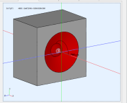
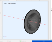
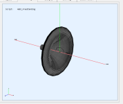
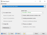
Data is exported in VACS, hit Graph > "Convert curves <-> contour", then IO > export. Screenshot from export data dialog attached, hit save from the bottom. Exported files need to be renamed from 001 format to hor001 type of thing vituixcad understands. Bulk renaming can be done with filerenamer, search the forum, I think fluid posted the original config for that but. Or, ask chatGPT for python script to do the renaming as excersize to get touch on modern AI agent world we live today.
Here VituixCAD setup, basically add three drivers, one for each spinorama set. Add some filters and a delay block to the woofer, hook the wires. Set Y-coordinates for the drivers relative your listening height. Here I just split in two, woofer center 26cm below ear, waveguide center 26cm above. I'm using hgh 1000Hz crossover as in previous examples, which ought to show worst effects regarding this subject.
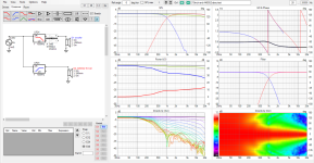
Now we already see from the above image the throat as rotation axis set works just fine as Z coordinates are still zero, since both woofer and the waveguide data was measured at 2m distance this is equivalent of real setup where the waveguide is above the woofer but brought forward so that throat is at baffle plane. Z (and X and Y) is basically adjustment for rotating axis and needs to set to reflect reality. So, if mouth is set to baffle plane, Z needs to be 200mm in this case, as the waveguide is 200mm deep from throat to mouth. Response gets out of whack so lets add 200mm of delay to woofer.
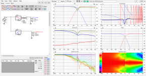
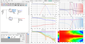
Compare this third image to first one to see effect of acoustic centers not at same plane.
Here with waveguide measured rotating axis at mouth plane
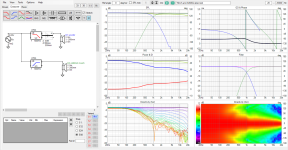
This looks almost the same as the throat with Z and delay as it should. There is slight difference due to different spin axis, as demonstrated in earlier posts the mouth spin data impulses advance in time with rotation until about 90deg.
So this is showing the same phenomenon like before, except it's not as dramatic as before. I do not know why, it's likely the data had some differences, like woofer simulated in diffraction tool and not in ABEC. Anyway, it's good thing the difference of acoustic centers being not on same axis is not too bad, not as bad as on my previous posts.
So, if there is error I'm repeating it, can anyone spot it? What I'm thinking is that why I do not need to delay woofer with mouth rotated waveguide data? Just zipping morning coffee so perhaps I figure it out later.
For ease of comparison, again throat aligned with woofer side by side with mouth aligned with the woofer, using throat rotated data:
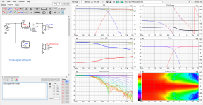
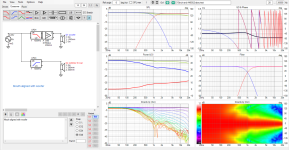
For completeness same for 500Hz crossover
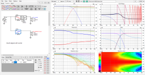
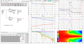
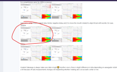
Here same using mouth rotated data. Notice negative delay and Z to move the mouth rotated to align throat with woofer, for ease.
1000Hz
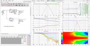
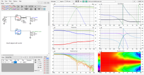
500Hz
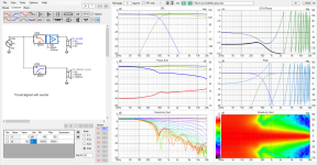
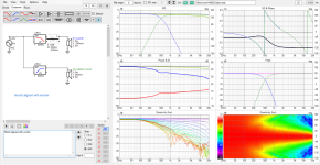
Greatest takeaway is always make sure data is legit!😀 Another one is, there is slight difference in data depending on waveguide rotating axis, DI changes a bit because off-axis measurements change a bit depending whether rotating axis is at acoustic center or not.
I redid ABEC sims and made fresh VituixCAD project to weed out any errors. Now the woofer is also simulated in ABEC instead of in vituixCAD and data done with same observation script as the waveguide. Observation definition is same that came when I ran ath definition that came with A460G2. Basically it's normalized 37 step 5deg 0-180 spinorama data with 2m measurement distance, both woofer and waveguide measured at their axis and same distance away like in VituixCAD measurement manual. The waveguide is simulated rotated both at mouth and the throat, so we have to adjust Z coordinate in VCAD to move the waveguide in simulator. Throat is the default, mouth rotation achieved Shifting nodes -200mm. Woofer is simplest possible way to do it with ABEC, solving.txt attached.


Data is exported in VACS, hit Graph > "Convert curves <-> contour", then IO > export. Screenshot from export data dialog attached, hit save from the bottom. Exported files need to be renamed from 001 format to hor001 type of thing vituixcad understands. Bulk renaming can be done with filerenamer, search the forum, I think fluid posted the original config for that but. Or, ask chatGPT for python script to do the renaming as excersize to get touch on modern AI agent world we live today.

Here VituixCAD setup, basically add three drivers, one for each spinorama set. Add some filters and a delay block to the woofer, hook the wires. Set Y-coordinates for the drivers relative your listening height. Here I just split in two, woofer center 26cm below ear, waveguide center 26cm above. I'm using hgh 1000Hz crossover as in previous examples, which ought to show worst effects regarding this subject.

Now we already see from the above image the throat as rotation axis set works just fine as Z coordinates are still zero, since both woofer and the waveguide data was measured at 2m distance this is equivalent of real setup where the waveguide is above the woofer but brought forward so that throat is at baffle plane. Z (and X and Y) is basically adjustment for rotating axis and needs to set to reflect reality. So, if mouth is set to baffle plane, Z needs to be 200mm in this case, as the waveguide is 200mm deep from throat to mouth. Response gets out of whack so lets add 200mm of delay to woofer.


Compare this third image to first one to see effect of acoustic centers not at same plane.
Here with waveguide measured rotating axis at mouth plane

This looks almost the same as the throat with Z and delay as it should. There is slight difference due to different spin axis, as demonstrated in earlier posts the mouth spin data impulses advance in time with rotation until about 90deg.
So this is showing the same phenomenon like before, except it's not as dramatic as before. I do not know why, it's likely the data had some differences, like woofer simulated in diffraction tool and not in ABEC. Anyway, it's good thing the difference of acoustic centers being not on same axis is not too bad, not as bad as on my previous posts.
So, if there is error I'm repeating it, can anyone spot it? What I'm thinking is that why I do not need to delay woofer with mouth rotated waveguide data? Just zipping morning coffee so perhaps I figure it out later.
For ease of comparison, again throat aligned with woofer side by side with mouth aligned with the woofer, using throat rotated data:


For completeness same for 500Hz crossover


Here same using mouth rotated data. Notice negative delay and Z to move the mouth rotated to align throat with woofer, for ease.
1000Hz


500Hz


Greatest takeaway is always make sure data is legit!😀 Another one is, there is slight difference in data depending on waveguide rotating axis, DI changes a bit because off-axis measurements change a bit depending whether rotating axis is at acoustic center or not.
Attachments
Last edited:
I could post the VituixCAD project with the data if it's ok to post as it contains sim results of A460G2?
I already posted it for a minute, but removed it to ask permission first just in case.
I already posted it for a minute, but removed it to ask permission first just in case.
All I know from my practical experience with many such designs, with real data, is that horizontally it's always possible to smoothly blend the complete polars of one source to the other. And if they are similar, it's basically seamless. I've never encountered anything else. So, to a large degree, I'm still wondering what you're actually doing here... I have no clue.
Sims are fine.I could post the VituixCAD project with the data if it's ok to post as it contains sims of A460G2?
Last edited:
Yeah and within relative accuracy it could be said from the above as well. Both mouth and throat aligned system blends smoothly.
If you look at the graphs above, there is some difference how they sum depending on how much acoustic centers differ. When they differ as in mouth at woofer plane, "issues" move toward listening window. When both acoustic centers coincide, throat at woofer plane, the issues move from listening winwdow to far off-axis, behind the system. Issues would be due to depth of the device mouth aligned to woofer making acoustic centers not align. Whether it's real issue it's another question, but it seems to be there, so something to take into account, especially with deep devices whose acoustic center is far from mouth.
If you look at the graphs above, there is some difference how they sum depending on how much acoustic centers differ. When they differ as in mouth at woofer plane, "issues" move toward listening window. When both acoustic centers coincide, throat at woofer plane, the issues move from listening winwdow to far off-axis, behind the system. Issues would be due to depth of the device mouth aligned to woofer making acoustic centers not align. Whether it's real issue it's another question, but it seems to be there, so something to take into account, especially with deep devices whose acoustic center is far from mouth.
Last edited:
Are you sure that the simulations and all the data are correct? The relative positions, Z offsets, etc. I don't know VituixCAD, I only got an impression this can get tricky. Your results seem strange to me but I don't have the capacity to go through it right now.
Yeah I'm pretty sure they are as should, purpose is to exactly follow best practice, how all sims with VituixCAD are supposed to be done.
It would be cool if someone checked them out just in case, I might repeat some error. I could post the exact VituixCAD project if it's fine for you? It contains simulated data of A460G2 which is your commercial product.
It would be cool if someone checked them out just in case, I might repeat some error. I could post the exact VituixCAD project if it's fine for you? It contains simulated data of A460G2 which is your commercial product.
Last edited:
Here VituixCAD project attached, it should contain all data. It would be cool if someone had time to see it and spot possible error. Also my posts, if they contain some error.
I'm using 2.0.118.3 version of VituixCAD, not the latest 2.0.118.4, but there should be no difference.
I'm using 2.0.118.3 version of VituixCAD, not the latest 2.0.118.4, but there should be no difference.
Attachments
How to combine woofer and waveguide into single ABEC project? Might be fun excersize, although takes some time so can't do it in near future.
It's already possible right in the Ath script (I would need to look that up) but the mesh size jumps up dramatically, as it's a 3D sim and only in half symmetry.
- This is it: https://www.diyaudio.com/community/...-design-the-easy-way-ath4.338806/post-7186017
You can also export all the FRD data from the script. I know @sheeple can do it. I don't remember.
- This is it: https://www.diyaudio.com/community/...-design-the-easy-way-ath4.338806/post-7186017
You can also export all the FRD data from the script. I know @sheeple can do it. I don't remember.
Last edited:
Yeah - I don't believe it. 🤓Believe it or not but the T34A provides even wider beamwidth with the right (very shallow) waveguide.
It's because its diaphragm is taller, which happens to be the major factor.
T25A also has a very high dome and while T34A has wider radiation as a normal 25mm tweeter ... not as the T25A ;-)
https://hificompass.com/en/speakers/measurements/bliesma/bliesma-t25a-6
https://hificompass.com/en/speakers/measurements/bliesma/bliesma-t34a-4
T34A feels unreal when listening to it off axis cause size of the driver does not correlate to what you hear. But T25A does even radiate wider.
p.s.: to stay on topic - a waveguide for the T25A would be really cool. Cause of the dome it performs horrible in all "normal" waveguides.
There is one error at least, this image reads "Mouth aligned" while it is throat aligned from the settings.
Another error is here:
I opened my yesterdays experiment again, and if I substitute the woofer data with this new ABEC generated one the error between yesterday and todays experiemnts show up.
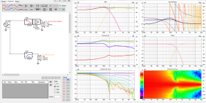
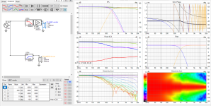
So, case almost closed, error found, and main suspect is mixing data from different simulators. Still there is some difference with the measurement rotation axis and how acoustic centers align with both yestedays and todays experiments, although opposite conclusions, so everyone, use the hawk eye with this stuff not to get confusing results like I've done here 😀 Especially with simulated data, also take care when measuring things.

Another error is here:
Actually, the 1000Hz crossover shows "issues" move toward listening window with throat aligned with woofer! Off-axis response lines are uniform when mouth is at woofer plane. This is opposite to my conclusion quoted, also opposite to posts from yesterday. This indicates there is error somewhere.If you look at the graphs above, there is some difference how they sum depending on how much acoustic centers differ. When they differ as in mouth at woofer plane, "issues" move toward listening window. When both acoustic centers coincide, throat at woofer plane, the issues move from listening window to far off-axis, behind the system. Issues would be due to depth of the device mouth aligned to woofer making acoustic centers not align. Whether it's real issue it's another question, but it seems to be there, so something to take into account, especially with deep devices whose acoustic center is far from mouth.
I opened my yesterdays experiment again, and if I substitute the woofer data with this new ABEC generated one the error between yesterday and todays experiemnts show up.


So, case almost closed, error found, and main suspect is mixing data from different simulators. Still there is some difference with the measurement rotation axis and how acoustic centers align with both yestedays and todays experiments, although opposite conclusions, so everyone, use the hawk eye with this stuff not to get confusing results like I've done here 😀 Especially with simulated data, also take care when measuring things.
Last edited:
I just had a quick look - it seems like all sims work as they should but not the 500Hz and negative delay one? Does negative delay work as it should in VituixCAD?Greatest takeaway is always make sure data is legit!😀 Another one is, there is slight difference in data depending on waveguide rotating axis, DI changes a bit because off-axis measurements change a bit depending whether rotating axis is at acoustic center or not.
But over all it shows that the concept of delay the woofer on a flat baffle works well?
It makes little sense to make a waveguide for T25A, because with T34A it will be just better in every regard, including the directivity. You may not believe it but it's true. Unintuitive, but real. That's what you get if you actually start messing with acoustics.p.s.: to stay on topic - a waveguide for the T25A would be really cool.
Last edited:
There is one "little" downside of the T34A - price! And size.because with T34A it will be just better in every regard,
For many speakers the T34 "monster" is simply not needed in terms of output and cross over frequency. I use the T25A for e.g. in my kitchen speakers or for small surround speakers which need wide radiation. It's a totally underrated tweeter, sounding better as most metal dome ones while not too expensive.
But I only use it with small midrange drivers to keep a steady off axis performance. To be able to use it with a bigger midrange would be an interesting possibility.
Thanks checking it IamJF!
Here is with negative and positive delay so the simulator works technically correct. Can you spot logic error how it's used with the 500Hz test, what's the error you see?
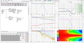
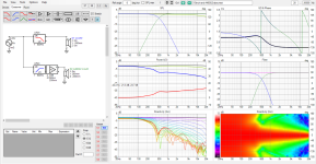
To explain, here the waveguide and woofer are both measured rotating through baffle plane and mouth plane. Hence, to move throat to baffle plane, the wavefuide data is brought 200mm closer to observer, and delayed 200mm to compensate for path legth difference.
This is inverse operation to throat spun data, where the waveguide needs to move 200mm further from observer to align mouth with woofer, and the woofer is delayed to compensate.
Yeah, the delay compensation works as it should making sound arrive at same time, except the arrival time varies little by measurement angle when waveguide acoustic center is behind woofer's, which is consistent with yesterdays experiment and what the Desmos example demonstrates. If you mute the woofer and let the waveguide play alone and go to impulse view. You see that the mouth rotated waveguide impulse gets earlier in time if you change Ref angle.
Here impulse at 0-deg ref angle for mouth rotated waveguide alone, and the other is at 50 deg angle the impulse arrives earlier, which means acoustic center got closer to microphone with the rotation.
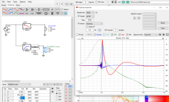
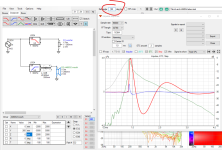
If the data is compensated by Z -offset, it behaves like the one measured with rotating around throat, the impulse stays until >90 deg it gets late.
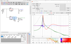
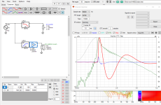
So yeah it works, except for the small difference the acoustic centers make, and it doesn't seem to be that bad here as it was yesterday 😀 So, perhaps more errors somewhere.
ps. sorry it gets bit off topic but I think it's worth it to find errors and not leave things floating mid air.
Here is with negative and positive delay so the simulator works technically correct. Can you spot logic error how it's used with the 500Hz test, what's the error you see?


To explain, here the waveguide and woofer are both measured rotating through baffle plane and mouth plane. Hence, to move throat to baffle plane, the wavefuide data is brought 200mm closer to observer, and delayed 200mm to compensate for path legth difference.
This is inverse operation to throat spun data, where the waveguide needs to move 200mm further from observer to align mouth with woofer, and the woofer is delayed to compensate.
Yeah, the delay compensation works as it should making sound arrive at same time, except the arrival time varies little by measurement angle when waveguide acoustic center is behind woofer's, which is consistent with yesterdays experiment and what the Desmos example demonstrates. If you mute the woofer and let the waveguide play alone and go to impulse view. You see that the mouth rotated waveguide impulse gets earlier in time if you change Ref angle.
Here impulse at 0-deg ref angle for mouth rotated waveguide alone, and the other is at 50 deg angle the impulse arrives earlier, which means acoustic center got closer to microphone with the rotation.


If the data is compensated by Z -offset, it behaves like the one measured with rotating around throat, the impulse stays until >90 deg it gets late.


So yeah it works, except for the small difference the acoustic centers make, and it doesn't seem to be that bad here as it was yesterday 😀 So, perhaps more errors somewhere.
ps. sorry it gets bit off topic but I think it's worth it to find errors and not leave things floating mid air.
Last edited:
Are you sure this post processing delivers the same result as a measurement with correct rotational axis?To explain, here the waveguide and woofer are both measured rotating through baffle plane and mouth plane. Hence, to move throat to baffle plane, the wavefuide data is brought 200mm closer to observer, and delayed 200mm to compensate for path legth difference.
Yep, price point is really an issue.There is one "little" downside of the T34A - price! And size.
- Home
- Loudspeakers
- Multi-Way
- Acoustic Horn Design – The Easy Way (Ath4)