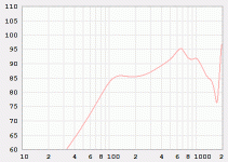
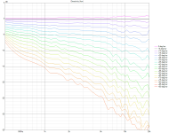
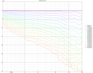
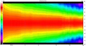
Further from the throat = less gain in the high frequencies?A590G2 approximated by two point expo (not preceise) - different position of midwoofer ranging 11 to 20cm from throat.
The problem in having the taps longer away from the throat is that they are further apart too.
You don't want them to be so far spread, as to produce dips off axis. This has been the biggest concern for me.
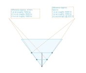
Bad illustration following:
On this 73 angle conical horn, 20cm long
First set of taps are at 5cm (7.5 cm apart), and the second at 10cm (15 cm apart)
At an arbitrary angle of 34.4 degrees off axis
Below 1/4 wavelength the two penings contribute to each other
At 1/2 wavelength, they are out of phase.
I'm a bit baffled by how the polars of this speaker tho:
https://www.audiosciencereview.com/...coaxial-horn-monitor-with-4x-5-woofers.29072/
Attachments
Last edited:
Further from the throat = less gain in the high frequencies?
Yes and depends on horn profile. As you know Bill Waslo in Cosynes got flat passband. I could not get flat from A590G2 waveguide in Hornresp. Actually the resonance is close to average from exponential sections used for approx:
Apologies if this is a bit too far off-topic. I recently noticed something interesting while doing harmonic distortion measurements of a compression driver on an OS waveguide: filling the CD throat with reticulated foam (~20mm deep) significantly increased the 3rd harmonic over the entire bandwidth of the device. This result was perfectly repeatable across multiple measurements and with two driver samples, so almost certainly cannot be explained by measurement error. Has anyone else measured something similar and/or have an idea about the exact mechanism?
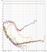
Here's the distortion without the foam. The test level was ~103dB SPL at 1 meter:

With the foam:

Note: red=2nd, orange=3rd, green=5th. At around 2.4kHz, the foam increased the 3rd harmonic by 12dB.
Here's the distortion without the foam. The test level was ~103dB SPL at 1 meter:
With the foam:
Note: red=2nd, orange=3rd, green=5th. At around 2.4kHz, the foam increased the 3rd harmonic by 12dB.
It seems to trade the even-order harmonics for the odd-order ones. Absolutely no idea what's going on.
I'm working on a mini Tritonia waveguide mold (200 x 178 x 65 mm, 1" throat).
It can be printed in one piece, so I decided to give it a try, as it seems to be really easy to do 🙂


It can be printed in one piece, so I decided to give it a try, as it seems to be really easy to do 🙂
I think that the printed horns are usable for critical listening, I wouldn't offer the kits if I thought otherwise. It may just require quite an amount of manual work, and that can be tedious, depending on how much you like it 🙂
If all goes well, I should be through printing the ATH A460 kit by the end of the day today. I printed using PLA. 4 layers wall thickness (0.4 nozzle) and 5 layers top and bottom (0.2mm layer height). 12% infill in the petals and 25% in the mouth.
For those who have attempted to put this kit together, is there a recommended procedure you think I should follow (e.g., glue all the petals first and then attach them to the base, or glue the petals to the base one by one, etc.)? Also, even though the print is coming out nice, it's never going to be 100%. Thus, is there a glue/epoxy that you all recommend that can both adhere to PLA well and still have some gap-filling properties?
Lastly, is there a reason why this piece was separated from the petal? I just want to make sure I think though why it was seperated and how it being seperated can help with the assembly.
I wondered about it as well 🙂Lastly, is there a reason why this piece was separated from the petal?
These parts just come out as a result of cutting the waveguide in a hexagonal grid. Due to this they are also smaller, and so are smaller the accuracy errors, in principe. So after all it may be a good thing. Take it as a feature.
Last edited:
Testing MEH idea with multiple apertures for A350G2. Sovol SV08 estimated print time for grey part is 7 hours vs 23h on bed slinger.

The even-order harmonic levels are closer when normalized (note the ~0.5-1dB drop in the fundamental level), but certainly does appear that way at certain frequencies. At around 1.4kHz, the normalized 2nd harmonic drops by about 2dB while the 3rd harmonic increases by about 5dB.It seems to trade the even-order harmonics for the odd-order ones.
Attachments
While I haven't tried putting foam into waveguides, I have seen that the foam used in resistance enclosures seems to increase distortion from the slits. When I did near-field measurements of the slits the third order in particular went up a lot compared to not using foam. I assume it's due to some kind of nonlinearity of the material as the sound propagates through it. The magnitude of the effect seems to depend on the foam used. I tried a couple of different ones.
I'm actually working on a resistive midrange enclosure as well, may try it when I'm into it. Interesting.


(The small Tritonia waveguide shown earlier is meant as an alternative to this.)
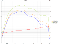
BTW, the predicted SPL for Dayton SIG180-4, horizontal polars (BEM + LE):


(The small Tritonia waveguide shown earlier is meant as an alternative to this.)
BTW, the predicted SPL for Dayton SIG180-4, horizontal polars (BEM + LE):
Last edited:
Here's a hint for those printing the A460. The only potentially problematic spot I found is this overhang:

I guess it can be managed by adjusting speeds and/or cooling (or adding supports, if nothing else works) but for me this solved itself simply by printing more of these parts together - it's more time for the filament to cool down. Just in case...
I guess it can be managed by adjusting speeds and/or cooling (or adding supports, if nothing else works) but for me this solved itself simply by printing more of these parts together - it's more time for the filament to cool down. Just in case...
Last edited:
It was a bothced glue up, but here are some measurements using peerless drivers (DFM-2535R00-08). These are quite old at this point. Also, these are meant to be quick and dirty measurements. I've taken a picture of the point of rotation. Ref angle is 10 degrees.


The edge of the plywood is the point of rotation.

The edge of the plywood is the point of rotation.
Attachments
- Home
- Loudspeakers
- Multi-Way
- Acoustic Horn Design – The Easy Way (Ath4)
