I told you maybe five times what that quantity ("SP") means. It is the frequency response of an ideal point source radiating the same total sound power as the source with the given/measured polars. What's not clear on that?
Suggestion: SPmabat: the power response of an imaginary point source radiating sound as per the given/measured polars.
It cant be the frequency response of an ideal point source because it's "perfect" and nothing is - so there is a contradiction in the definition.
You definition is also problematic in the sense that it is circular - i.e. using the concept to be defined in the definition itself - rookie misstake - an other oppsie...
//
Is there a way to make the BEE enclosure have a square top/bottom rather than a radius? I'm also a confused about the BEE enclosure. Is it a special case of Mesh.Enclosure Marcel wrote as an experiment on passive cardioid or something else? Also, I feel dumb. What does BEE mean, Baffle Enclosure Experiment was all my itsy-bitsy brain could come up with.
; LF enclosure type "BEE"
BEE = {
Height = 500 ; [mm]
Radius = 125 ; [mm]
Depth = 250 ; [mm]
Source = 90 ; diaphragm radius [mm]
YOffset = -420 ; [mm]
ZOffset = 40 ; [mm]
; mesh resolution: top-front, top-back, bottom-back, bottom-front
Resolution = 20,30,50,50
; dipole opening
Port = {
z = 25 ; [mm]
w = 40 ; [mm]
wt = 15 ; wall thickness [mm]
Resolution = 35 ; [mm]
;Weight = 0.8 ; driving weight (default=1.0)
Damping = 0.5 ; interior wall damping
}
}
In a post a couple pages back #12110 I incorrectly believed Early Reflections Directivity Index was effectively a measure of how a speaker behaved between two states: either the sound source theoretically effectively emits sound within a beam width, with no sound emitted beyond a certain angle, or a sound source that emits sound with a smooth linear gradient of say -0.3dB/degree off axis from 0-180 degrees. This got me thinking, although it doesn't effect directivity measures it could be used as a way to design speakers of a desired DI and optimise the listening window at the same time.
Here are the two states:
Fixed beam:


Gradient Beam:


In both cases DI and ERDI are derived from differences between the listening window and Power/ER total respectively, this gave similar DI's in both cases, the lowest level set for the fixed beam was -54dB same as the gradient beam, the power response does differ between the two models I've created which makes the comparison a little more difficult. Both of these states are not realistic, but the infinite set of bell-curves that could exist in transition from one to the other are more realistic, a bell curve with a closer approximation to the fixed beam would have a lesser deviation of listening window, as long as the fixed beam width it's approximating is +/-30 degrees as to not change the listening window, this does limit how high the DI this could be used for. With an approximation closer to the gradient beam, which is closer to actual behaviour, there is a large deviation in listening window. What I'm thinking here is that a bell curve with the desired DI and listening window could used as a guide, higher DI would require an approximation closer to FB for a flatter listening window, and an approximation closer to GB for a lower DI and flat listening window.
could this be a good way of thinking about polar response design for a wave guide?
Also would a good target for a listening window at 20kHz be around -1.5dB from the on axis sound?
If you managed to read all of that thanks and thanks again for any thoughts.
Here are the two states:
Fixed beam:
Gradient Beam:
In both cases DI and ERDI are derived from differences between the listening window and Power/ER total respectively, this gave similar DI's in both cases, the lowest level set for the fixed beam was -54dB same as the gradient beam, the power response does differ between the two models I've created which makes the comparison a little more difficult. Both of these states are not realistic, but the infinite set of bell-curves that could exist in transition from one to the other are more realistic, a bell curve with a closer approximation to the fixed beam would have a lesser deviation of listening window, as long as the fixed beam width it's approximating is +/-30 degrees as to not change the listening window, this does limit how high the DI this could be used for. With an approximation closer to the gradient beam, which is closer to actual behaviour, there is a large deviation in listening window. What I'm thinking here is that a bell curve with the desired DI and listening window could used as a guide, higher DI would require an approximation closer to FB for a flatter listening window, and an approximation closer to GB for a lower DI and flat listening window.
could this be a good way of thinking about polar response design for a wave guide?
Also would a good target for a listening window at 20kHz be around -1.5dB from the on axis sound?
If you managed to read all of that thanks and thanks again for any thoughts.
One positive result of this debate is that Hornresp will get fixed
Only if it can be established that the existing directivity model does indeed need fixing.
Just to clarify, the example provided earlier assumed half space, not free space conditions. Under free space conditions the Hornresp pressure response equals the power response plus directivity index.
The Hornresp directivity model was developed using information provided in the classic "Acoustics" reference book written by Leo Beranek. Extracts from that book and from the more recent Beranek and Mellow updated text, are included in this post.
As indicated in the image below, the directivity factor and hence also directivity index are normally determined assuming a free space environment.
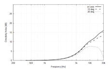
This means that when considering other than free space conditions, the on-axis directivity index values change as shown in the next two images. Trace (5) in the second image shows the DI assuming free space conditions and trace (3) shows the DI assuming half space conditions.
Hornresp currently takes the solid radiation angle into account when calculating the DI, as shown in the next two images. For half space conditions and ka = 5 (at 4423 Hz for the piston size being used in the test example) the results are the same as those given above. In the case of the DI chart, the grey trace shows the free space DI values and the black trace shows the half space DI values.
Assuming that the Hornresp half space power response calculations are correct (they have been validated for bass horns on many occasions by users comparing simulation predictions to measured results) and that the half space DI curve as given by Beranek and Mellow above is correct, then all that remains is to establish how best to combine the power response and DI values to obtain a pressure response. If there is an error in the Hornresp model, then that is where it is likely to be.
The seemingly obvious answer is to simply take the free space power response and add the half space DI values to obtain the half space pressure response. This would give the correct result if the acoustic power radiated by the source remained the same when the solid angle was changed, but this is not the case in practice. At lower frequencies the output power increases as the solid radiation angle is reduced, due to the improved radiation impedance loading conditions.
Many options were considered and tested before arriving at the one that was finally adopted in Hornresp, and while it gives entirely consistent and robust results for all solid angles it does mean that only under free space conditions will the difference between the power response and the pressure response be the same as the DI.
The method currently used in Hornresp to calculate the pressure response under half space conditions first reduces the half space DI values by 3 dB and then adds those adjusted values to the half space power response.
(It might seem easier to simply use the free space DI values rather than offsetting the half space DI values by -3 dB, but the free space values differ somewhat from the -3 dB offset values at higher frequencies).
The image below shows the power and on-axis pressure response results obtained under half space conditions using the existing method. As expected, the pressure response (black trace) is effectively the same as the power response (grey trace) until the directivity characteristics of the system become a contributing factor at higher frequencies.
Any suggestions on how to fix the Hornresp directivity model if indeed it needs fixing, would be greatly appreciated.

For the CEA2034 the SPDI is actually the Listening Window (LW) that is used not the On-axis (ON)."Sound Power Directivity Index (SPDI) is normally defined as the difference between
the on-axis curve and the sound-power curve, expressed in dB."
This is why I added DI ON which is the "normal" definition.
Request: ATH config script as close as possible to JBL 305P MkII
Goal: Example to help learn the advanced features of ATH
Explanation: I'm currently trying to learn how to make enclosures in ATH and thought an example script of a common speaker would be helpful. It can be anything but my first thought is the JBL 305P MkII might be good because 1) rear port unnecessary because it's on the rear, 2) Erin's Audio and ASR both have Klippel measurements, 3) soft dome tweeter, 4) a complex waveguide surface, 5) inexpensive and easy to obtain. In addition, both Erin's Audio and ASR have measurements for the JBL 708P which might be helpful as an additional example because it uses a compression driver. Unfortunately, it has a forward facing port. Consequently, someone with more knowledge may have a better example suggestion than the JBLs. Also, someone with more knowledge may say this is a bad idea because it would be impossible to model a commercial speaker closely enough that it wouldn't cause confusion for newbies like myself. In which case, please ignore me.
One positive result of this debate is that Hornresp will get fixed
Dr Bjørn Kolbrek, co-author of the quite remarkable "High Quality Horn Loudspeaker Systems - History, Theory & Design" book, was kind enough to some time ago give me a copy of a simulation program that he had created and continues to develop for his own personal use.
Dr Kolbrek is a recognised authority on horn loudspeaker theory and design. In the past he has worked as a senior research engineer on the design and development of horn loudspeakers at Celestion International in the United Kingdom. He has presented papers on horn loudspeaker design and horn loudspeaker simulation at AES Conventions.
Out of interest I have now simulated in his HornCAD program the test example I used in Post #12,185.
The half space pressure response results calculated by HornCAD are virtually identical to those produced by Hornresp. If the Hornresp directivity model is wrong then so is the one independently developed by Dr Kolbrek, which I very much doubt would be the case, given his unquestioned knowledge and experience.
Thank you David for the comparison.Dr Kolbrek is a recognised authority on horn loudspeaker theory and design. In the past he has worked as a senior research engineer on the design and development of horn loudspeakers at Celestion International in the United Kingdom. He has presented papers on horn loudspeaker design and horn loudspeaker simulation at AES Conventions.
Out of interest I have now simulated in his HornCAD program the test example I used in Post #12,185.
Ath would show an actual power response in accordance with CEA-2034.... and what would ATH show?
//
David McBean - does your model use stacked cylindrical elements in its calculations? I seem to remember that it did. And I suspect that Bjorn also uses the same technique. Thus one would expect them to produce the same results.
But these techniques are nowhere near as accurate as the BEM ones that Marcel uses.
But these techniques are nowhere near as accurate as the BEM ones that Marcel uses.
There is the question of whether Marcel is simulating the right thing in the right way in this particular case. Only saying because this wouldn't be the first time or the first thread where I've seen the way people interpret CTA2034 brought into question.
does your model use stacked cylindrical elements in its calculations?
The test example used in Posts #12,185 and #12,188 calculated results for a circular piston in an infinite plane baffle, not for a horn / waveguide system. To answer your specific question though, Hornresp does not use stacked cylindrical elements in any of its models.
But these techniques are nowhere near as accurate as the BEM ones that Marcel uses.
Agreed, that was never in question.
Ath would show an actual power response in accordance with CEA-2034.
What would be really interesting to see is what Ath shows for the power response, on-axis pressure response and on-axis directivity index of a circular piston in an infinite plane baffle.
I case this could be useful after Erin from https://www.erinsaudiocorner.com/ asked for it, I published my CEA2034 Octave/Matlab script here:
https://www.audiosciencereview.com/...-cea2034-from-the-nfs-data.14141/#post-985452
It is believe to be accurate as at least two other persons have very similar results (ASR users MZKZ and Pierre from https://www.spinorama.org/).
The Klippel NFS provides identical results save for the ER (and therefore PIR). I believe my script correct as it is made in accordance to the verification made by the Harman people that worked on the standard (calculation of ER).
I don't know if that was corrected by Klippel.
VituixCAd also does a similar job https://kimmosaunisto.net/Software/Software.html but I believe that the author @kimmosto made some modifications to the metric.
Excellent, thanks.
The 2 x Pi on-axis directivity index chart would appear to be incorrect. As shown in Post #12,185 by definition the minimum on-axis DI value for a circular piston in an infinite plane baffle can never be less than 3 dB.
Attachments
- Home
- Loudspeakers
- Multi-Way
- Acoustic Horn Design – The Easy Way (Ath4)