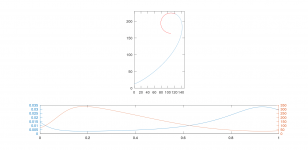
- Some more perspective from the past, the real measured response of the Sandhorn:
https://www.diyaudio.com/community/...-design-the-easy-way-ath4.338806/post-6773405 🙂
https://www.diyaudio.com/community/...-design-the-easy-way-ath4.338806/post-6773405 🙂
Yes, OB, possibly with some attempt to utilize the back side radiation for a cardioid-like structure.Are you going with an open baffle?
If you should choose a sealed or resistance cab the old trusted BMS 18N862 is hard to beat. It’s fairly light moving mass (260g) and low Fs (25Hz) but not the cheapest on the market.
That BMS is way out of my budget for this - I'm using several more LF subs so I don't need to go that far - I basically don't care much about the response below 50 Hz. I just need something with big enough diaphragm that doesn't take more space than necessary. Could be closed, I just like the OB idea better.
Hi, yes, also before the new plot I was interested about it but the new plot looked so interesting it triggered to study the ripple origin. On the new plot it was kind of easy to see.The 'fall' plots make ripples more visible. @tmuikku made me think about diffraction with his remarks that seem to have been triggered by the fall plots.
Do you happen to have charts for smaller version of the same waveguide to demonstrate? 90deg seems louder further away, perhaps its just nearfiel/farfield stuff? The waveguide is rather big isn't it, R=225?Also note that the level of fall-off is dependent on the distance. I think this has to do with the relative size of the waveguide wrt the listening distance (and again Pythogaros).
Pythagoras answers to lot of things. Using it all the time figuring out listening spot vs. speaker position, for example estimating effect of beaming and lobing effects to real listening situation. It is very nice to accompany thinking process with some simple math 🙂
Difference between diffraction ripple and ripple due to sound around the waveguide is that diffraction shows in listening window as well while sound around the device mostly off-axis, outside listening window. Very little comes all the way around I think. On device like this there is more sound to the edge and around the back on long wavelengths while higher frequencies are projected more forward. Sound around the waveguide seems to happen roughly diameter size wavelength. Strongest diffraction just like with any objects, like direct radiator on a baffle we get "the diffraction hump".I think we would have to minimize the ripples to minimize the 'reflection' and then use some other mechanism to control the sound around the backside of the waveguide, e.g. tmax>1 and some absorption? Now I think of it, although the sound around the backside has never been reflected, it is a delayed version of the direct sound; which is what a reflection is also. So do we actually have to absorb that sound to limit the time domain problem?
This device size wavelength diffraction seems to cancel itself out to the off-axis because the part that goes around is roughly equivalent to the backwave of the diffraction and they would cancel out on a well optimized waveguide like ST260. But the diffraction backwave is not like direct sound proportion of the diffraction that goes around. Diffraction backwave also radiates to listening window where there is no sound around the device to cancel it out.
What is audible and what is not, I have no comment. Most waveguides in the thread with very small ripple are already miles ahead to anything else I've seen yet. With the backside optimization the little there was left seems to be gone. Perhaps choose by ease of manufacture or aesthetic reasons like mabat and fluid propose.
Last edited:
As we've seen its possible to have a waveguide whose DI is nice with diffraction because sound around the device compensates. Reduce either and DI gets wonky. We need both to balance each other out, or reduce both altogether, for smoothest results on screen.
Something for Ripplebusters - it also helps to round the outer edge:


And what about a circle/torus from the point of highest curvature circling in on the backside of the waveguide? Can we put some absorbing material in the simulation?
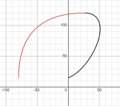
To extend the back side you can fiddle with the existing parameters, mainly increase b and reduce r (and maybe decrease q):
https://www.desmos.com/calculator/oyjukmcbgh
The advantage being a smooth curvature progression.

(The body would probably have to be closed at the back so that it doesn't form a resonant cavity. That can be tweaked manually in the sim.)
https://www.desmos.com/calculator/oyjukmcbgh
The advantage being a smooth curvature progression.
(The body would probably have to be closed at the back so that it doesn't form a resonant cavity. That can be tweaked manually in the sim.)
Last edited:
Yeah, perfect example of waveguide with no secondary sounds. But you get beaming. I wouldn't say its useless, its just not constant directivity. DI is without a glitch, couldn't be much smoother than that. Now its just matter to find out if more constant directivity was possible with it, the mouth and beoyond is fine on the curve but profile near the throat makes beam. Preaching to choir 🙂
I haven't had time to try just circular backside for say ST260, ought to work but not sure before trying. If separate back side curve worked it might enable waveguide curve to be optimized for more constant directivity while still effectively smoothing the DI, I think. One could use tmax=1 with R-OSSE and then add simple circular arc for the back. Wouldn't be continuous curve but perhaps close enough.
edit. I think diffraction effect to the DI has been important part making wide bandwidth constant directivity narrowing the response on the low end. If the secondary sounds are reduced we'd need some new tricks for similar directivity as before, don't know. If the diffraction is removed perhaps devices need to be bit bigger than before since there is no extra narrowing effect from the secondary sounds.
Last edited:
Perhaps small throat compression drivers (less than 1") with small mids. There is an interesting biamp patent on using m200 midrange compression drivers firing into a horn using small slits. Perhaps these mids could also be compression drivers?
https://www.diyaudio.com/community/...per-scripts-and-m200-fun.385493/#post-7009215 here is a post by Kyle talking about the midrange compression drivers as MEH mids.
Crossover is listed a 1.84khz so close to where a small comp could take over.
Crossover is listed a 1.84khz so close to where a small comp could take over.
Yes, that's a conclusion I already made in the past, based on my various experiments. There's simply something that the "t=1" termination does right.I think diffraction effect to the DI has been important part making wide bandwidth constant directivity narrowing the response on the low end.
Perhaps just a small round lip would be enough (e.g. to continue a little further at the maximum curvature).
One more -
Last edited:
And what about a circle/torus from the point of highest curvature circling in on the backside of the waveguide?
I have all the math ready:

How do I get this in ath or ABEC3?
Edit: that is exactly what I meant @mabat! I didn't refresh the page before posting this...
How do you calculate the point of max curvature? I can do it only numerically (haven't even tried to solve it analytically).
I have no special powers... I eyeballed it 🙂
I'll see if I can convince (wx)Maxima to find it for us.
Edit:
Nope...
I'll see if I can convince (wx)Maxima to find it for us.
Edit:
Nope...
Code:
Message from the stdout of Maxima\: Welcome to LDB, a low\-level debugger for the Lisp runtime environment.
\(GC in progress\)
ldb\>
Message from maxima's stderr stream: Heap exhausted during garbage collection: 0 bytes available, 16 requested.
Gen  Boxed   Cons    Raw   Code  SmMix  Mixed  LgRaw LgCode  LgMix  Pin       Alloc     Waste        Trig   Dirty GCs Mem-age
 1       0  17404      0      0      0      4      0      0      0   26   565669776   4755568    20971520  557056   0  0.9253
 2       0   7583      0      0      0      2      0      0      0   23   246448368   2096912    20971520       5   0  0.3043
 3      15  23056     37      7     14     13      0      0      0  149   751845408   6471648     2000000    1193   0  0.5339
 4       0      0      0      0      0      0      0      0      0    0           0         0     2000000       0   0  0.0000
 5       0      0      0      0      0      0      0      0      0    0           0         0     2000000       0   0  0.0000
 6     469    185    291    708    102     20     35      0     62    0    60322944   1018752     2000000     525   0  0.0000
 7       0  13993      0      0      0      0      0      0      0    0   454940416   3582208     2000000  447776   0  0.0000
           Total bytes allocated    =    2079226912
           Dynamic-space-size bytes =    2097152000
GC control variables:
   *GC-INHIBIT* = true
   *GC-PENDING* = true
   *STOP-FOR-GC-PENDING* = false
fatal error encountered in SBCL pid 3488839508:
Heap exhausted, game over.
Last edited:
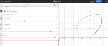
I managed to add bezier curve for the backside in Desmos but not sure if its any help. https://www.desmos.com/calculator/e2dygvmtlh
Scroll to bottom, few parameters to change the curve.

Basically added this https://www.desmos.com/calculator/lavlfhvstv to your R-OSSE example without knowing much about what am I doing. Idea was to be able to make sure the driver fits in without affecting the waveguide part.
edit. Seeing it there in desmos the transition looks sudden most of the time and probably diffracts. Some eyeballed parameters look nice and smooth though.

Scroll to bottom, few parameters to change the curve.

Basically added this https://www.desmos.com/calculator/lavlfhvstv to your R-OSSE example without knowing much about what am I doing. Idea was to be able to make sure the driver fits in without affecting the waveguide part.
edit. Seeing it there in desmos the transition looks sudden most of the time and probably diffracts. Some eyeballed parameters look nice and smooth though.

Last edited:
Observation on the max curvature thing. On the good waveguides the max curvature seems to happen quite close to the lip and it can be quite tight. If you use the max curvature and stick it there wouldn't it make quick turn around on the lip? Perhaps its fine for optimizers to seek out answers though. Might be hard to determine length of the extra part though? Just thinking out loud.
edit. hey, how about if you check out curvature just on last point (tmax) and use tmax to zone in on the max curvature, until the roundover is nice? Well but again where to end the curve then.. perhaps you are already on to it 🙂
edit. hey, how about if you check out curvature just on last point (tmax) and use tmax to zone in on the max curvature, until the roundover is nice? Well but again where to end the curve then.. perhaps you are already on to it 🙂
Last edited:
- Home
- Loudspeakers
- Multi-Way
- Acoustic Horn Design – The Easy Way (Ath4)