200hz, 1,300 hz, both 96dB/oct Linkwitz-Riley FIRArea51, what frequencies for x-over does it use?

Why not IIR filters + a global phase linearisation by FIR? Just curious about your strategy.
//
//
They certainly are
I had this problem with my previous attempts, but I believe I fixed it with the current Area-51 version.
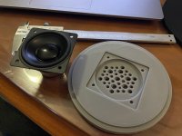
I've attached some measurements and photos of the previous version. I was lazy with the design and extended the midrange taps/ports far enough so everything could be mounted flat on the rear.
View attachment 1119901View attachment 1119902
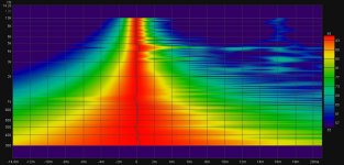
There was some kind of cancellation at 4400hz
View attachment 1119904
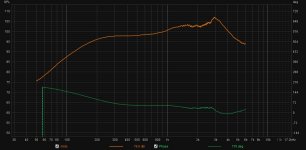
Here are two measurements, one with tape covering the ports
View attachment 1119905
Reducing the port length, also slightly smaller diameter, seemed to fix it
View attachment 1119910
Hi SubTweeter, So impressive, very nice, this Area 51 build !!
I think you've done what a number of folks want to....and what we will see more and more of.....printed ATH/(MEH-Unity-Syn) builds.
Thanks for posting this previous version too. The notch at 4400Hz is intriguing. It's so deep and narrow. I haven't seen anything like that playing with small mid ports on conical horns.
I keep trying to picture the 4.4k's 3 inch wavelength, and how it might interact with those ports, to make a notch like that.
Do you think the fix came entirely from reducing the port length, and the slightly smaller diameter?
Did the distance from the ports to CD change any? Or the distance port to port?
Sorry for all the questions, but a couple more... when you measured the notch, were the 3" drivers mounted?
If they were mounted, were they shorted out? (I've found not shorting all driver section can make for some whacky measurements)
But in what you show, the tape fixed the notch entirely. Really curious here! Thx
Here's a 2:35:1 ratio I've been working on tonight.
1" throat, 490mm x 210m x 120mm deep, gcurve super formula.
Six iterations later... interesting shape developing.
Wish I knew how to use the API...


1" throat, 490mm x 210m x 120mm deep, gcurve super formula.
Six iterations later... interesting shape developing.
Wish I knew how to use the API...
Last edited:
Why not IIR filters + a global phase linearisation by FIR? Just curious about your strategy.
//
I just like using rePhase to do EQ, filters & flatten phase all in one filter, then just load them into EqualizerAPO.
The notch at 4400Hz is intriguing. It's so deep and narrow. I haven't seen anything like that playing with small mid ports on conical horns.
I keep trying to picture the 4.4k's 3 inch wavelength, and how it might interact with those ports, to make a notch like that.
Do you think the fix came entirely from reducing the port length, and the slightly smaller diameter?
Did the distance from the ports to CD change any? Or the distance port to port?
Sorry for all the questions, but a couple more... when you measured the notch, were the 3" drivers mounted?
If they were mounted, were they shorted out? (I've found not shorting all driver section can make for some whacky measurements)
But in what you show, the tape fixed the notch entirely. Really curious here! Thx
Don't mind answering questions at all, I am new to posting here and only meant to show how well the ATH horn worked so if this is going off topic to the thread I apologise.
My best guess is the internal volume of the port and chamber next to the speaker cone was acting like a Helmholtz absorber at 4.4k. An impedance measurement of both the mid's and compression driver showed nothing abnormal at 4.4k, but as you can see in the graph below something is happening at 4.4k to cause a cancellation
Attachments
If you're willing to sacrifice 1-2dB of output, you can fill the midrange taps with polyester fibrefill. (Same stuff that's in pillows - you can buy it at Wal Mart.)
Since the mids in a Unity horn are capable of 115+ dB of output, this can be a viable method of taming resonances.
Since the mids in a Unity horn are capable of 115+ dB of output, this can be a viable method of taming resonances.
Always wanted to try this... but not that worried now as the new shorter port version does not have this problemIf you're willing to sacrifice 1-2dB of output, you can fill the midrange taps with polyester fibrefill. (Same stuff that's in pillows - you can buy it at Wal Mart.)
Since the mids in a Unity horn are capable of 115+ dB of output, this can be a viable method of taming resonances.
Hey guys
regarding port design maybe smalle but distributed may equalize some effects..
https://patents.google.com/patent/US9894433B2/en?oq=PATENT:+US9894433B2
They had a nice white paper about it but I cannot find it anymore
regarding port design maybe smalle but distributed may equalize some effects..
https://patents.google.com/patent/US9894433B2/en?oq=PATENT:+US9894433B2
They had a nice white paper about it but I cannot find it anymore
Interesting. I've never considered the idea of ports forming some sort of Helmholtz...My best guess is the internal volume of the port and chamber next to the speaker cone was acting like a Helmholtz absorber at 4.4k.
Cool. Thx. The little ports ducts almost seem like paths like a a CD phase plug.Hey guys
regarding port design maybe smalle but distributed may equalize some effects..
https://patents.google.com/patent/US9894433B2/en?oq=PATENT:+US9894433B2
They had a nice white paper about it but I cannot find it anymore
I tried something akin to the simple holes prior art drawing in the patent.
An air-bake pizza pans over different port shapes, used with a 10" low (the dang frowny face worked very well, not sure why i abandoned it)

Hi TNT, to keep from too much off-topic on my part. gonna start a new thread to hopefully give an answer...Why not IIR filters + a global phase linearisation by FIR? Just curious about your strategy.
//
Hi! Got an answer from Subtweeter to which it was aimed. But please, its an interesting subject!!
//
//
The Chinsese Distributor still has most of it on their websiteThey had a nice white paper about it but I cannot find it anymore
http://pro-pa.com/index.php?id=2059
This picture shows the construction quite well
I got as far as making a CAD sketch knockoff, maybe one day I'll get round to testing some of these half finished ideas 🙂
Been meaning to try a PK Sound midrange integrator knockoff too but never finished it as I went back to the Area-51 design, even made a big 600mm ATH rollback waveguide to test it with. I got as far as printing half of it and measuring a little test print with the array of holes
Attachments
SubTweeter, do you attribute the frequency response slope differences between the Area 51 and the PK sound to the port differences or the driver differences?
Area 51 - 3" midrange

PK sound - 2" midrange

Area 51 - 3" midrange
PK sound - 2" midrange
Bose has done some interesting stuff with this concept too. They have some patents on waveguides where the waveguide itself becomes increasingly perforated as you go from "throat" to "mouth."
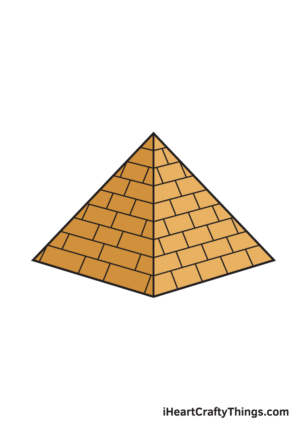
If you look at an audio waveguide as a series of pyramids, this makes sense.
Basically:
1) the directivity of high frequencies is shaped by the first 10% of the waveguide or so. By the time that the wavefront has travelled 5cm or so, the shape of the high frequencies is basically set in stone.
2) Same applied for midrange and low frequencies, they're shaped as the wavefront travels further down the waveguide
3) High frequencies don't "see" holes that are smaller than a fraction of their wavelength. IE, when a compression driver radiates a wavefront that's 17cm in length (2000Hz) the wavefront can't "see" a hole that's 2cm in diameter. The hole is just too small.
So you balance all of these things, and you can perforate a waveguide like it was swiss cheese, as long as the high frequencies have already been "shaped" and the mid and low frequencies are too small to "see" the holes. This is why the location and size of the taps in a Unity horn is a balancing act. It's not just about putting them as close to the tweeter as possible, in some cases you WANT them to be further away so that the high frequencies don't "see" the holes.
Oh was already tried over here. But my basic idea was not a complete perforated area as pk did. I think stickibg to area 51 design but a slightly larger area with 2-10 holes. So a combination basically.
You might want to reduce the volume of the chamber formed by the midrange cone. Also the longer the pathway, the larger the resonance.
So hopefully the peak is shifted above the frequency of the midrange driver operation. Something I normally do is to angle the holes, so that they are not perpendicular to the horn wall, but rather looking out.
I'm not sure how much it helps to do teardrop shaped holes instead of circles. I've done both, but never really compared.
The frequency response of the midrange is a tradeoff between how deep in the horn the holes are (loading by the horn) and how big the chamber/port size and length are.
It's basically a miniature 4-th order bandpass subwoofer design.
- Home
- Loudspeakers
- Multi-Way
- Acoustic Horn Design – The Easy Way (Ath4)