Same thing happened to me with ABEC demo version but the exact same thing solved fine in AKABAK. Weird, nothing looks wrong with it.Hi,
I tried to solve the script but got garbage, or at least I can't understand the results.
I am using gmsh-4.6.0-Windows64 and Ath 4.9.0-pre-release-221114.
I's most likely the rounding of your corners. Increase the radius and it will improve.Interesting. Just to make sure we are on the same point: I am not concerned about the splash >10k, which is a mere artifact of the resolution. I mean the strong wiggles between 2 and 8 kHz.
The mesh does not include thin triangles that should be problematic:
View attachment 1114046
What you could focus on instead is the narrowing at 1k 🙂
It seems that I indeed had reducedI's most likely the rounding of your corners. Increase the radius and it will improve.
Code:
FrontResolution = 10,10,20,20
Code:
FrontResolution = 8,8,16,16If you have a workaround at hand, parameter-wise, I am all ears. However, I found that I could never reduce the waistbanding magnitude at the -3db threshold to be less than ~5-6 degrees, compared with the pattern width above. It appears to me to be a limitation of size. Only feasible solution I had found was pushing it down out of the passband of its intended use: making the waveguide walls longer. The baffle width is the limitation here. It could also be masked by a wider dispersion at the lower end, but this also means a pattern that gradually narrows. I am not after this, it is either too wide at the bottom or too narrow at the top. Crossed with the right slopes (here: 4th order on the tweeter at 1.25, 3rd order on the woofer at 1.35 kHz), it is not a big issue. At least at the -6 dB threshold it is only 3 degrees narrower.What you could focus on instead is the narrowing at 1k
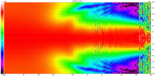
For the sound power, the solution can be as easy as using a different profile on the vertical axis. The extra energy there (also slightly oriented at kimmos rule, where he proposed a wider radiation pattern for the tweeter at the crossover) fills the gap. This is what I get in VCad for the same crossover:
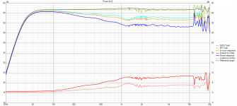
The best pattern / sound power at crossover result I have achieved in simulation so far. Not a JBL M2, but for a ten-inch this is looking good to my eyes.
Hi sheeple! Could you share your workflow? I'd love to combine ath4 design/analysis with vituixCAD verification too.The best pattern / sound power at crossover result I have achieved in simulation so far. Not a JBL M2, but for a ten-inch this is looking good to my eyes.
I think something is messing up the report for VACS.Same thing happened to me with ABEC demo version but the exact same thing solved fine in AKABAK. Weird, nothing looks wrong with it.
With my cfg it seems to (mostly, Z?) work:
Code:
;Optimized for fast iteration
;See Ath manual for details

; -------------------------------------------------------
; R-OSSE BLD parameters
; -------------------------------------------------------

R-OSSE = {
  R  = 130 ; [mm]
  a  = 39.5 ; [deg]
  r0 = 12.7 ; [mm]
  a0 = 8 - 35*sin(1*p)^4; [deg]
  k  = 3 ; []
  r  = 0.25 ; []
  m  = 0.82 ; []
  b  = 0.29 ; []
  q  = 4.5 ; []
         }

Source.Shape          = 1

; -------------------------------------------------------
; Mesh Settings
; -------------------------------------------------------
Mesh.LengthSegments   = 36
Mesh.AngularSegments  = 48
Mesh.ThroatResolution = 5
Mesh.MouthResolution  = 12
Mesh.RearResolution   = 15
Mesh.WallThickness    = 8

Mesh.SubdomainSlices  = 35
Mesh.InterfaceOffset  = 25
Mesh.InterfaceDraw    = 0
Mesh.RearShape        = 2

; -------------------------------------------------------
; ABEC Project Settings
; -------------------------------------------------------
ABEC.SimType          = 2
ABEC.MeshFrequency    = 1000     ; [Hz]
ABEC.f1               = 600      ; [Hz]
ABEC.f2               = 10500    ; [Hz]
ABEC.NumFrequencies   = 45
ABEC.Abscissa         = 1

ABEC.Polars:SPL_H     = {
MapAngleRange         = 0,180,37 ; 5deg resolution
                        }

ABEC.Polars:SPL_V     = {
MapAngleRange         = 0,180,37 ; 5deg resolution
Inclination           = 90       ; [deg]
                        }

; -------------------------------------------------------
; Output
; -------------------------------------------------------
Report                = {
Title                 = "Athcfg2try"
NormAngle             = 0   ; [deg]
MaxAngle              = 180 ; [deg]
DrvImp_Range          = 10
Width                 = 1024
Height                = 768
GnuplotCode           = 3x2n.gpl
                        }

Output.SubDir         = "Optimizer-Output"
Output.STL            = 0
Output.ABECProject    = 1
Did not try the Gnuplot report though...
Any comment are welcomed
Create 4 ABEC polar observation sets in wg.cfg, for a full spin.Hi sheeple! Could you share your workflow? I'd love to combine ath4 design/analysis with vituixCAD verification too.
- tweeter +-180 vertical degree
- tweeter +-180 horizontal degree
The same for the woofer, all normalized to 0 degree axis.
From Ath 4.9, define the LFSource.B as SID = 1 and include the SID command in both tweeter (always SID = 0) and woofer obervations.
https://www.diyaudio.com/community/...he-easy-way-ath4.338806/page-541#post-7169897
Start calculating full spin 20-20k with frequency resolution of your choice, return later, ath [your waveguide .cfg path] -r and in the ABEC results folder, there is now FRD for both drivers.
Name them properly in the ath script so VCad automatically recognizes them (check VCad options), i.e. use NamePrefix = tweeter_ver (... tweeter_hor, woofer_ver, woofer_hor).
You can now search for either tweeter / woofer via Windows explorer search function in the FRD folder that was created by Ath in the ABEC Results folder. Select all (woofer / tweeter), cut and move them to a seperate folder. Go to VCad, add new driver, add all tweeter FRDs from one folder, add new driver, add all woofer FRDs from other folder. Done.
Last edited:
If you streetch your budget some you can get this https://en.toutlehautparleur.com/speaker-phl-audio-3411-8-ohm-10-inch.html
Sorry - to clarify, I was looking for compression driver recommendations, to mate with the ST260B.
I am using the Celestion CDX1-1747 as a cheaper alternative to B&C 250. It cannot be crossed very low, c. 1.25 kHz with LR24. I enjoy the sound but have no comparison.
The B&C 250 currently is 105 EUR and it can play much lower. Low fs is also the Tymphany DFM-2544R00-08, a bit cheaper but currently on backorder. Its smaller sibling DFM-2535R00 was a cheap alternative but is now only available in bulk.
The B&C 250 currently is 105 EUR and it can play much lower. Low fs is also the Tymphany DFM-2544R00-08, a bit cheaper but currently on backorder. Its smaller sibling DFM-2535R00 was a cheap alternative but is now only available in bulk.
Quick question before having to read 550 posts (again)
How important is the throat angle of the st260 waveguide? This waveguide has a throat angle of 19 degrees, would that be a mismatch with my drivers that have 21 degrees exit? How much better is the CE series compared to the ST?
I tried to get a request for a CE waveguide with 21 degrees throat angle at at-horns.eu but they do not respond to emails so I’m left with the ST design or look somewhere else
Hi,
Mabat simulated the angles at some point and difference was minimal, you might find them searching with exit angle.
If it is your last speaker you ever build and the exact waveguide and driver you end up using then its worth it to optimize everything like exit angle. If not then I wouldn't sweat about 2deg difference if itnis big task to change it.
That said, I ordered 3D printed ST260 with 30 deg exit angle which I thought was better match for my drivers but double checking afterwards the original would have been closer 😀 I ordered cheap prints for prototyping and intend to order new ones later on so not a biggie. There is issues in frequency response on top octave, not sure if its the angle mismatch or just the driver resonance which is there even in driver datasheet.
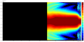
My issue with the wiggles prevails after increasing the resoultion of the rounded corners in half-symmetry. This is the results of waveguide in quarter-symmetry, free field:
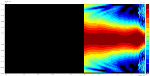
This is mostly the same mesh (more resolution at rounded corners, frequencies = 200) in half-symmetry:
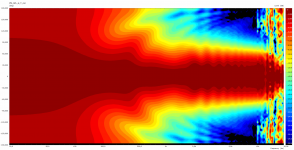
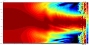
Also, phase issue is still in the data:
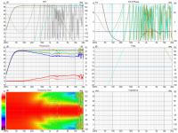
Is someone running Ath on Win11? The only change to my system lately.


This is mostly the same mesh (more resolution at rounded corners, frequencies = 200) in half-symmetry:


Also, phase issue is still in the data:

Is someone running Ath on Win11? The only change to my system lately.
I had used the following config file:
Code:
; ____ Parameters ____


Throat.Angle = 10.08
Throat.Diameter = 25.4
Throat.Profile = 1
Coverage.Angle = 57                 -18*sin(p)^2

Length = 51.5
Term.s = 3.2                         +0.4*sin(p)^2
Term.n = 3.7                         +0.5*sin(p)^2
OS.k = 0.20                             -0.1*sin(p)^2
Term.q = 0.87674


; ____ Source Mode ____

Source.Shape = 1
Source.Curv = 0
Source.Radius = -1
Source.Velocity = 1

; ____ Enclosure ____

Mesh.Enclosure = {
Spacing = 27,30,27,367 ; edge distances (left,top,right,bottom)
Depth = 270
EdgeRadius = 25
EdgeType = 1
FrontResolution = 8,8,16,16
BackResolution = 20,20,30,30

LFSource.B = {
    Spacing = 70
    Radius = 106.5
    DrivingWeight = 1.0
    SID = 1
 }
}

; ____ LE Model ____

LE = generic25

; ____ 3D Mesh Settings ____

Mesh.LengthSegments = 30
Mesh.AngularSegments = 48
Mesh.ThroatResolution = 4
Mesh.MouthResolution = 8
Mesh.SubdomainSlices =

Mesh.ZMapPoints = 0.5,0.1,0.76,0.733
Mesh.Quadrants = 14

; ____ Measurement Axis ____

Mesh.VerticalOffset = 126.5

; ____ ABEC Settings ____

ABEC.MeshFrequency = 1000
ABEC.NumFrequencies = 200
ABEC.SimType = 2
ABEC.f1 = 20
ABEC.f2 = 20000

; ____ VCAS Output ____


ABEC.Polars:SPL H T = {
  SID = 0
  MapAngleRange = 0,180,72
  Distance = 2.0
 }

 ABEC.Polars:SPL V T = {
   SID = 0
  MapAngleRange = 0,180,72
  Distance = 2.0
  Inclination = 270
 }


ABEC.Polars:SPL H W = {
  SID = 1
  MapAngleRange = 0,180,72
  Distance = 2.0
 }

 ABEC.Polars:SPL V W = {
  SID = 1
  MapAngleRange = 0,180,72
  Distance = 2.0
  Inclination = 270
 }


ABEC.Polars:SPL_H_T_nor= {
  SID = 0
  MapAngleRange = -180,180,72
  Distance = 2
  NormAngle = 0

    FRDExport = {
    NamePrefix = hor_tweeter
  }
}


ABEC.Polars:SPL_V_T_nor = {
  SID = 0
  MapAngleRange = -180,180,72
  Distance = 2
  Inclination = 270
  NormAngle = 0

    FRDExport = {
    NamePrefix = ver_tweeter
  }
}


ABEC.Polars:SPL_H_W_nor = {
  ;SID = 1
  MapAngleRange = -180,180,72
  Distance = 2
  NormAngle = 0

    FRDExport = {
    NamePrefix = hor_woofer
  }
}


ABEC.Polars:SPL_V_W_nor = {
  ;SID = 1
  MapAngleRange = -180,180,72
  Distance = 2
  NormAngle = 0
  Inclination = 270

    FRDExport = {
    NamePrefix = ver_woofer
  }
}


; ____ Ath Report ____

Report = {
  Title = "60DG"
  Width = 1200
  Height = 800
  NormAngle = 0
}

; ____ File Output ____

Output.ABECProject = 1
Output.STL = 0You can now search for either tweeter / woofer via Windows explorer search function in the FRD folder that was created by Ath in the ABEC Results folder. Select all (woofer / tweeter), cut and move them to a seperate folder. Go to VCad, add new driver, add all tweeter FRDs from one folder, add new driver, add all woofer FRDs from other folder. Done.
Thanks! Initial import seems ok.
https://www.diyaudio.com/community/threads/ath4-waveguide-inspired-multi-way.384410/post-7190892
Thanks! Initial import seems ok.
https://www.diyaudio.com/community/threads/ath4-waveguide-inspired-multi-way.384410/post-7190892
Looking good. If you cannot increase vertical spacing, you could consider an asymmetric crossover to fill in the missing sound power in the crossover region with the downward vertical lobe.
Would you mind sharing your mesh settings? Maybe I set mine up in a wrong manner? Still not getting around the issue I have currently ...
Code:
Mesh.Enclosure = {
  Spacing = 20,20,20,344
  Depth = 275
  EdgeRadius = 18
  EdgeType = 1
  FrontResolution = 8,8,14,14
  BackResolution = 25,25,25,25
  LFSource.B = {
    Spacing = 25
    Radius = 135
    DrivingWeight = 1
    SID = 1
  }
}
Mesh.AngularSegments = 96
Mesh.LengthSegments = 20
Mesh.ThroatResolution = 2.5
Mesh.InterfaceResolution = 7.0
Mesh.InterfaceOffset = 5.0
Mesh.ZMapPoints = 0.5,0.1,0.5,0.99
Mesh.SubdomainSlices =
Mesh.Quadrants = 14
Last edited:
Hi @mabat can you check to see if LFSource.B works with my_plan cabinets? Here's my current cfg.
Code:
; -------------------------------------------------------
; Enclosure Setting
; -------------------------------------------------------

my_plan = {
  point  P0 166 0 16
  point  P1 184 18 16
  point  P2 184 30 24
  point  P3 63.79 293 24
  point  P4 45 300 24
  point  PB 0 300 24
  cpoint C1 166 18
  cpoint C2 -163.8 30
  cpoint C3 45 271.3
  arc P0 C1 P1
  line P1 P2
  arc P2 C2 P3
  arc P3 C3 P4
  line P4 PB
}

Mesh.Enclosure = {
  Plan = my_plan
  Spacing = 0,20,0,344
  FrontResolution = 16,16,16,16
  BackResolution = 24,24,24,24
  LFSource.B = {
    Spacing = 25
    Radius = 135
    DrivingWeight = 1
    SID = 1
  }
}

; -------------------------------------------------------
; Measurement Settings
; -------------------------------------------------------
Mesh.VerticalOffset = 0

; -------------------------------------------------------
; Mesh Setting
; -------------------------------------------------------
Mesh.AngularSegments = 96
Mesh.LengthSegments = 20
Mesh.ThroatResolution = 5.0 ; [mm]
Mesh.InterfaceResolution = 10.0 ; [mm]
Mesh.InterfaceOffset = 5.0 ; [mm]
Mesh.ZMapPoints = 0.5,0.1,0.5,0.99

Mesh.SubdomainSlices =
Mesh.Quadrants = 14                     ; 1/2 symmetry

; -------------------------------------------------------
; ABEC Project Setting
; -------------------------------------------------------

ABEC.SimType = 2
ABEC.Abscissa = 2 ; 1=log | 2=linear
ABEC.f1 = 1000 ; [Hz]
ABEC.f2 = 12000 ; [Hz]
ABEC.MeshFrequency = 1000
ABEC.NumFrequencies = 12

ABEC.Polars:SPL H T = {
  SID = 0
  MapAngleRange = 0,180,72
  Distance = 3
 }

ABEC.Polars:SPL V T = {
  SID = 0
  MapAngleRange = 0,180,72
  Distance = 3
  Inclination = 270
 }

ABEC.Polars:SPL H W = {
  SID = 1
  MapAngleRange = 0,180,72
  Distance = 3
 }

ABEC.Polars:SPL V W = {
  SID = 1
  MapAngleRange = 0,180,72
  Distance = 3
  Inclination = 270
 }

ABEC.Polars:SPL_H_T_nor= {
  SID = 0
  MapAngleRange = -180,180,72
  Distance = 3
  NormAngle = 0
    FRDExport = {
    NamePrefix = hor_tweeter
  }
}

ABEC.Polars:SPL_V_T_nor = {
  SID = 0
  MapAngleRange = -180,180,72
  Distance = 3
  Inclination = 270
  NormAngle = 0
    FRDExport = {
    NamePrefix = ver_tweeter
  }
}

ABEC.Polars:SPL_H_W_nor = {
  SID = 1
  MapAngleRange = -180,180,72
  Distance = 3
  NormAngle = 0
    FRDExport = {
    NamePrefix = hor_woofer
  }
}

ABEC.Polars:SPL_V_W_nor = {
  SID = 1
  MapAngleRange = -180,180,72
  Distance = 3
  NormAngle = 0
  Inclination = 270
    FRDExport = {
    NamePrefix = ver_woofer
  }
}

; -------------------------------------------------------
; Output
; -------------------------------------------------------

Output.DestDir = "C:\ath4" ; current directory by default

Output.STL = 1
Output.ABECProject = 1

Report = {
  Title = "my_plan"
  Width = 1200
  Height = 800
  NormAngle = 0
}
Last edited:
4.8.3b2 using demo1.cfg profile. I can't seem to get the woofer SID to carry over to the 3D mesh. Any help would be greatly appreciated.
Code:
; -------------------------------------------------------
; Horn Geometry
; -------------------------------------------------------

Throat.Profile = 1
Throat.Diameter = 25.4
Throat.Angle = 10
Coverage.Angle = 45
Length = 100
Morph.TargetShape = 1

; -------------------------------------------------------
; Enclosure Setting
; -------------------------------------------------------

my_plan = {
  point  P0 166 0 12
  point  P1 184 18 12
  point  P2 184 30 24
  point  P3 63.79 293 24
  point  P4 45 300 24
  point  PB 0 300 24
  cpoint C1 166 18
  cpoint C2 -163.8 30
  cpoint C3 45 271.3
  arc P0 C1 P1
  line P1 P2
  arc P2 C2 P3
  arc P3 C3 P4
  line P4 PB
}

Mesh.Enclosure = {
  Plan = my_plan
  Spacing = 0,20,0,344
  FrontResolution = 24,24,24,24
  BackResolution = 24,24,24,24
  LFSource.B = {
    Spacing = 35
    Radius = 125
    DrivingWeight = 1
    SID = 1
  }
}

; -------------------------------------------------------
; Measurement Settings
; -------------------------------------------------------
Mesh.VerticalOffset = 0

; -------------------------------------------------------
; Mesh Setting
; -------------------------------------------------------
Mesh.AngularSegments = 96
Mesh.LengthSegments = 60
Mesh.ThroatResolution = 5.0 ; [mm]
Mesh.InterfaceResolution = 7.0 ; [mm]
Mesh.InterfaceOffset = 5.0 ; [mm]
Mesh.ZMapPoints = 0.3,0.5,0.5,0.95
Mesh.SubdomainSlices =
Mesh.Quadrants = 14

; -------------------------------------------------------
; ABEC Project Setting
; -------------------------------------------------------

ABEC.SimType = 2
ABEC.Abscissa = 1 ; 1=log | 2=linear
ABEC.f1 = 20 ; [Hz]
ABEC.f2 = 16000 ; [Hz]
ABEC.MeshFrequency = 1000
ABEC.NumFrequencies = 19

ABEC.Polars:SPL H T = {
  SID = 0
  MapAngleRange = 0,180,72
  Distance = 3
 }

ABEC.Polars:SPL V T = {
  SID = 0
  MapAngleRange = 0,180,72
  Distance = 3
  Inclination = 270
 }

ABEC.Polars:SPL H W = {
  SID = 1
  MapAngleRange = 0,180,72
  Distance = 3
 }

ABEC.Polars:SPL V W = {
  SID = 1
  MapAngleRange = 0,180,72
  Distance = 3
  Inclination = 270
 }

ABEC.Polars:SPL_H_T_nor= {
  SID = 0
  MapAngleRange = -180,180,72
  Distance = 3
  NormAngle = 0
  FRDExport = {
    NamePrefix = hor_tweeter
  }
}

ABEC.Polars:SPL_V_T_nor = {
  SID = 0
  MapAngleRange = -180,180,72
  Distance = 3
  Inclination = 270
  NormAngle = 0
  FRDExport = {
    NamePrefix = ver_tweeter
  }
}

ABEC.Polars:SPL_H_W_nor = {
  SID = 1
  MapAngleRange = -180,180,72
  Distance = 3
  NormAngle = 0
  FRDExport = {
    NamePrefix = hor_woofer
  }
}

ABEC.Polars:SPL_V_W_nor = {
  SID = 1
  MapAngleRange = -180,180,72
  Distance = 3
  NormAngle = 0
  Inclination = 270
  FRDExport = {
    NamePrefix = ver_woofer
  }
}

; -------------------------------------------------------
; Output
; -------------------------------------------------------

Output.DestDir = "C:\ath4" ; current directory by default

Output.STL = 1
Output.ABECProject = 1

Report = {
  Title = "my plan"
  Width = 1200
  Height = 800
  NormAngle = 0
}Ability to designate SID = 1 to woofer was introduced in release 4.9.
for earlier versions generate FRDs for each way separately, as described here: https://www.diyaudio.com/community/...he-easy-way-ath4.338806/page-541#post-7169375
for earlier versions generate FRDs for each way separately, as described here: https://www.diyaudio.com/community/...he-easy-way-ath4.338806/page-541#post-7169375
Last edited:
- Home
- Loudspeakers
- Multi-Way
- Acoustic Horn Design – The Easy Way (Ath4)