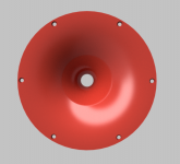
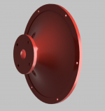
The idea of doing a big waveguide in multiple pieces has got me tinkering with larger, free standing waveguides.
Here is one.
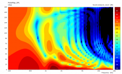
The config file is set to a beamwidth of 110 degrees, but I'm using a variable beamwidth that's based on angle. I do this to achieve the square-ish shape. I tried using a waveguide that was round, but the square-ish waveguide proved to be flatter. (I'm not sure what voodoo Mabat is using to get such flat response from a round symmetrical waveguide 🙂 )


Here's the log:
C:\Users\johnv\Downloads\Ath-4.7.1>ath.exe demos\aug13.cfg
Ath 4.7.1 beta4 32bit
--------------------------------------------------
Freeware version for personal non-commercial use
--------------------------------------------------
-destination directory: output\demos\aug13
-initializing
-fixed length: 127 mm
-calculating profiles
-max length after rollback: 119.214 mm
-writing ABEC project
-writing geo file bem_mesh.geo
-final mesh average throat angle: 15.000 deg
-reading source definition script
-adding rear side surface
-running 'C:\progra~1\gmsh\gmsh.exe bem_mesh.geo -'
Info : Running 'C:\progra~1\gmsh\gmsh.exe bem_mesh.geo -' [Gmsh 4.8.4, 1 node, max. 1 thread]
Info : Started on Fri Aug 13 00:37:41 2021
Info : Reading 'bem_mesh.geo'...
-setting mesh elements for radial drive
-running 'C:\progra~1\gmsh\gmsh.exe mesh.geo -'
Info : Running 'C:\progra~1\gmsh\gmsh.exe mesh.geo -' [Gmsh 4.8.4, 1 node, max. 1 thread]
Info : Started on Fri Aug 13 00:37:44 2021
Info : Reading 'mesh.geo'...
Done.
Final width x height = 404.8 x 404.8 mm (15.938 x 15.938")
Final length = 119.2 mm (4.693")
Here's the config file:
Throat.Profile = 1
Throat.Diameter = 34 ; [mm]
Throat.Angle = 15 ; [deg]
Coverage.Angle = 55.5 - 12*sin(p)^4 - 12*cos(p)^4
Length = 127 ; [mm]
Term.s = 0.95
;Term.n = 1.0 + 1.0*sin(p)^4
Term.n = 4.0
Term.q = 0.996
Rollback = 1
Rollback.StartAt = 0.6
Rollback.Angle = 135
Source.Contours = {
zoff -2
point p1 4.68 0 2
point p2 0 14 0.5
point p3 1 15 0.5
point p4 0 16 0.5
point p5 0 17 1
cpoint c1 -18.59 0
cpoint c2 0 15
arc p1 c1 p2 1.0
arc p2 c2 p3 0.75
arc p3 c2 p4 0.25
line p4 p5 0
line p5 WG0 0
}
Morph.TargetShape = 0
; -------------------------------------------------------
Mesh.AngularSegments = 64
Mesh.LengthSegments = 20
Mesh.ThroatResolution = 4.0 ; [mm]
Mesh.InterfaceResolution = 16.0 ; [mm]
Mesh.InterfaceOffset = 22.0 ; [mm]
; -------------------------------------------------------
ABEC.SimType = 2
ABEC.f1 = 500 ; [Hz]
ABEC.f2 = 16000 ; [Hz]
ABEC.NumFrequencies = 61
ABEC.MeshFrequency = 1000 ; [Hz]
ABEC.Polars:SPL = {
MapAngleRange = 0,90,11
;NormAngle = 10 ; [deg]
Distance = 2 ; [m]
}
; -------------------------------------------------------
Output.SubDir = "demos"
Output.STL = 1
Output.ABECProject = 1
Here is one.
The config file is set to a beamwidth of 110 degrees, but I'm using a variable beamwidth that's based on angle. I do this to achieve the square-ish shape. I tried using a waveguide that was round, but the square-ish waveguide proved to be flatter. (I'm not sure what voodoo Mabat is using to get such flat response from a round symmetrical waveguide 🙂 )
Here's the log:
C:\Users\johnv\Downloads\Ath-4.7.1>ath.exe demos\aug13.cfg
Ath 4.7.1 beta4 32bit
--------------------------------------------------
Freeware version for personal non-commercial use
--------------------------------------------------
-destination directory: output\demos\aug13
-initializing
-fixed length: 127 mm
-calculating profiles
-max length after rollback: 119.214 mm
-writing ABEC project
-writing geo file bem_mesh.geo
-final mesh average throat angle: 15.000 deg
-reading source definition script
-adding rear side surface
-running 'C:\progra~1\gmsh\gmsh.exe bem_mesh.geo -'
Info : Running 'C:\progra~1\gmsh\gmsh.exe bem_mesh.geo -' [Gmsh 4.8.4, 1 node, max. 1 thread]
Info : Started on Fri Aug 13 00:37:41 2021
Info : Reading 'bem_mesh.geo'...
-setting mesh elements for radial drive
-running 'C:\progra~1\gmsh\gmsh.exe mesh.geo -'
Info : Running 'C:\progra~1\gmsh\gmsh.exe mesh.geo -' [Gmsh 4.8.4, 1 node, max. 1 thread]
Info : Started on Fri Aug 13 00:37:44 2021
Info : Reading 'mesh.geo'...
Done.
Final width x height = 404.8 x 404.8 mm (15.938 x 15.938")
Final length = 119.2 mm (4.693")
Here's the config file:
Throat.Profile = 1
Throat.Diameter = 34 ; [mm]
Throat.Angle = 15 ; [deg]
Coverage.Angle = 55.5 - 12*sin(p)^4 - 12*cos(p)^4
Length = 127 ; [mm]
Term.s = 0.95
;Term.n = 1.0 + 1.0*sin(p)^4
Term.n = 4.0
Term.q = 0.996
Rollback = 1
Rollback.StartAt = 0.6
Rollback.Angle = 135
Source.Contours = {
zoff -2
point p1 4.68 0 2
point p2 0 14 0.5
point p3 1 15 0.5
point p4 0 16 0.5
point p5 0 17 1
cpoint c1 -18.59 0
cpoint c2 0 15
arc p1 c1 p2 1.0
arc p2 c2 p3 0.75
arc p3 c2 p4 0.25
line p4 p5 0
line p5 WG0 0
}
Morph.TargetShape = 0
; -------------------------------------------------------
Mesh.AngularSegments = 64
Mesh.LengthSegments = 20
Mesh.ThroatResolution = 4.0 ; [mm]
Mesh.InterfaceResolution = 16.0 ; [mm]
Mesh.InterfaceOffset = 22.0 ; [mm]
; -------------------------------------------------------
ABEC.SimType = 2
ABEC.f1 = 500 ; [Hz]
ABEC.f2 = 16000 ; [Hz]
ABEC.NumFrequencies = 61
ABEC.MeshFrequency = 1000 ; [Hz]
ABEC.Polars:SPL = {
MapAngleRange = 0,90,11
;NormAngle = 10 ; [deg]
Distance = 2 ; [m]
}
; -------------------------------------------------------
Output.SubDir = "demos"
Output.STL = 1
Output.ABECProject = 1
I pray every morning 🙂I'm not sure what voodoo Mabat is using to get such flat response from a round symmetrical waveguide
BTW, I won't fill the petals of the ST260. After the epoxy coating, it's pretty dead (and it wasn't bad even before), I really don't see a need for any improvement. With the CE360, I'll see what I get.
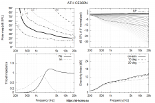
There's been a lenghty discussion about what DI is the most suitable for the current state of the reproduction industry. I think the following might be an alternative to the almost flat DI as in the CE series.
CE360N (1" throat, ⌀362 x 118 mm, work in progress) -
(Maybe this is already too much of a rise, I really don't know. Would love to hear both and compare directly, which may actually happen in a near future.)
CE360N (1" throat, ⌀362 x 118 mm, work in progress) -
(Maybe this is already too much of a rise, I really don't know. Would love to hear both and compare directly, which may actually happen in a near future.)
Attachments
TNT, Kimmosto demonstrated earlier this year that smoother power response can be achieved with cc ~1.4 wl, and worst case is about .5-.7 if i remember, this removes need to push the waveguide over the woofer unless you can drop down the xo enough to achieve near 1/4 wl c-c with the ath waveguide. Less diffraction problems at least.
Good then I can go back to the original...
//
Attachments
With or without a rolled-back lip?
Well both, actually, would be interesting to see.
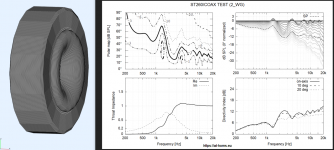
The axisymmetric case is quite extreme, it won't be nearly as bad in a rectangular box IMHO, but nevertheless.
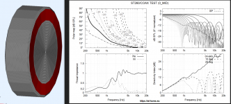
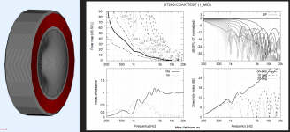
Three scenarios:
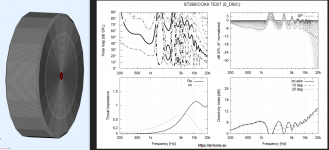
0 = no waveguide
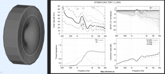
1 = flush mouth (no lip)
2 = rolled-back lip
The outer dimensions are always the same (⌀400 mm), WG is ⌀260 mm at its outer edge.
First, driven the midrange (red) area -
Three scenarios:
0 = no waveguide
1 = flush mouth (no lip)
2 = rolled-back lip
The outer dimensions are always the same (⌀400 mm), WG is ⌀260 mm at its outer edge.
First, driven the midrange (red) area -
Attachments
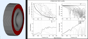

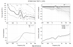
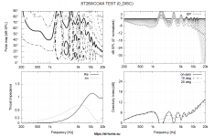
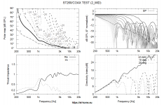


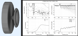
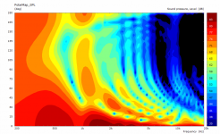
One thing is clear, I think - it's not the best idea to place a waveguide intended as free standing "flush mount" into a baffle. It's still better to use a flat edge WG in that case. And then round the edges of the enclosure heavily.
The second takeaway for me is that up to about 800 Hz it doesn't make any difference in this case (the wavelength is so long that it just doesn't matter).
The second takeaway for me is that up to about 800 Hz it doesn't make any difference in this case (the wavelength is so long that it just doesn't matter).
Last edited:
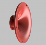
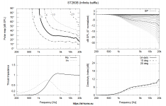
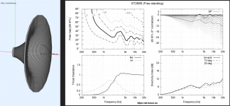
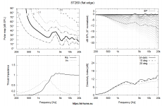
ST260B
ST260 for baffle mounting, ⌀260 x 82 mm (STL + STEP files): https://at-horns.eu/ext/ST260B.zip
ST260 for baffle mounting, ⌀260 x 82 mm (STL + STEP files): https://at-horns.eu/ext/ST260B.zip
Attachments
Those simulations above are I assume for a freestanding WG aimed for IB or is it in an IB like mounted in the middle of a wall?
//
//
Do the roll-back/non-roll-back simulations show that the advantage of roll-back is from about 2K and up, i.e. that a horn with operating range to e.g. 1.5K could be made without roll-back and still perform top notch?
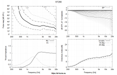
#7787-7791 are free (full) space
#7793 is in infinite baffle
Given that ST260 is best used with 12", could you pop the sim with ST260B on a baffle 35cm wide mounted on the upper part of 1m tall baffle ?
- Home
- Loudspeakers
- Multi-Way
- Acoustic Horn Design – The Easy Way (Ath4)