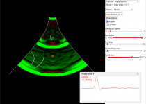
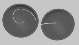
It's best to watch this live, there's quite a lot going on there - just open the attached code in #7311 (ripple_code.txt) in the Ripple Tank applet. Unfortunately, as discussed earlier, some of it will be "real" but some may be just artefacts of the simulation and you may never know which is which. That's the reason I haven't pursued it any furher.
Last edited:
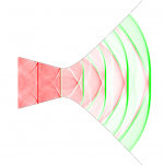
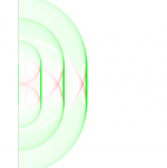
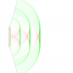
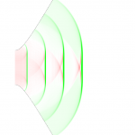
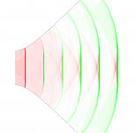
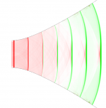
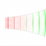
Some higher-resolution data (i.e. driven with a series of short "packets" of sound) -
Attachments
Last edited:
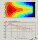
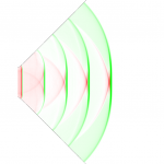
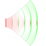
These are all the "higher order stuff" (including reflections) originating from mismatched wavefront curvatures or along curved walls. This is clearly seen from the progression of the wave.
Attachments
Last edited:

All of this would be observed as a small ripple in the decay of the impulse response. It's all delayed because of the longer paths. This is also what the foam plug attenuates (at least in principle), as Earl talked about for so many times.
So we need a WG wall that behaves like and absorber in some direction but solid/guiding in an other... suppose it doesn't exists... or the Geddes foam plug should be asymmetrical wrt. density in different directions?
//
//
Last edited:
Maybe the ultimate WG is not "open" but a body of mesh/foam that is structure wrt density and shape to create wave guidance. Like you barely can see through it really and perhaps with some, hopefully mostly resistive, linear loss but with very low reflections and very controlled dispersion... multi-cell (10000?) on steroids...
3D printable?
//
3D printable?
//
I think all of this is actually of very low level in the better waveguides so maybe it's not an issue after all. I personally haven't heard the effect of the foam plug in the waveguides I tried it in - at least not something I would be able to tell instantly. But I don't listen very loud as, I'm sure, some people do - perhaps it gets more audible at higher levels, that's what I didn't try.
The foam does the trick simply by damping more what has to travel longer path through it (then the question is how much is that really effective).
The foam does the trick simply by damping more what has to travel longer path through it (then the question is how much is that really effective).
Last edited:
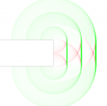
This wasn't really clear to me until now - how there could be a continuum when the coverage angle approaches a flat baffle. What I didn't realize was that there's a secondary radiation on the edge of a baffled piston as well - it's not a point source. Now it's so obvious 
OS throat: 30 - 60 - 90 - 120 - 150 - flat baffle
OS throat: 30 - 60 - 90 - 120 - 150 - flat baffle
Attachments
Last edited:

So a piston in a flat baffle is really the worst case. That makes me think quite differently about waveguides now! 🙂
Last edited:
BTW, apparently it doesn't get much worse if the piston is placed at the end of a tube (which may be the proper way of doing it after all, if omni is the goal).
Attachments
Last edited:
I suppose then, for a room, that a piston in a wall is as good, if not better, as one in a tube - given you aim for omni?
//
//
^^yep, the more panel around the driver the more interference and delayed sound to the listening window was my conclusion from baffle diffraction experiments 🙂 if narrow enclosure is not possible, roundovers /slants should start as close to the radiator as possible for minimum baffle diffraction problems.
- As we discussed phase plugs and the standing waves inside the compression cavity (and utilization of this knowledge for positioning the slits), can anyone imagine how to measure where the nodes actually are in a real driver?
Perhaps some measurement jig with a pressure probe could be used in the place of the phase plug, I don't know. Most probably this would be quite a tedious task. But possible?
Perhaps some measurement jig with a pressure probe could be used in the place of the phase plug, I don't know. Most probably this would be quite a tedious task. But possible?
Last edited:
I think that I would use small holes through which a probe tube is inserted. Then plug all the holes not in use. A large gap will modify the resonances to a large degree.
- Home
- Loudspeakers
- Multi-Way
- Acoustic Horn Design – The Easy Way (Ath4)