BTW, one question arise
what is benefit of flat wavefront in simulation.'?
I have no any clue what is shape of wavefront after phase plug of CD but seems very unlikely to be flat. As I know most of CD's have concave or convex membrane which moving axially so wouldn't axially moving spherical cap be most similar?
what is benefit of flat wavefront in simulation.'?
I have no any clue what is shape of wavefront after phase plug of CD but seems very unlikely to be flat. As I know most of CD's have concave or convex membrane which moving axially so wouldn't axially moving spherical cap be most similar?
...
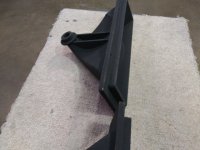
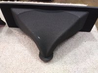
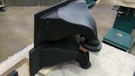
5. TD-2001 & HF10AK on RCF H3709...
The RCF H3709 is a straight throat clone of the Altec/WE 32 series.
The latter has been printed with another binder jetting 3D printing technology called AMClad, which is (also) sand-based.
Picture no. 4 shows the original on top of the printed horn.
Attachments

Last edited:
I have no any clue what is shape of wavefront after phase plug of CD but seems very unlikely to be flat. As I know most of CD's have concave or convex membrane which moving axially so wouldn't axially moving spherical cap be most similar?
The intent of virtually all phase plugs is a flat equ-phase wavefront at the exit aperture. How well it is achieved is complicated to the point that I have never seen it measured.
Sorry Marcel, I miss this point. What am I seeing in that link. Remember, at 70, I have a mem... What was I saying!
I think the idea is to build a horn that extends into the compression driver itself - essentially reducing the driver's throat length.

OK, yes, but nobody does that. That's why I looked for drivers with as short of a throat as possible - longer is a problem as we can see.
It would not be a problem to print such an insert into an existing driver. That was my point. When we make the whole waveguides, this is just one small detail more.
Last edited:
It would not be a problem to print such an insert into an existing driver. That was my point. When we make the whole waveguides, this is just one small detail more.
I'd love to see someone try it and post the results. It is a very good idea.
that insert seems like really good idea. It will be very easy to make it on lathe machine (and probably more precise than 3D printing).
It will make entry angle 0 for all CDs where is applicable so, as I understand, naturally better for the flat wavefront.
To not squeeze the exit to much maybe will be the best to take 1.4" CD and implement such insert
It will make entry angle 0 for all CDs where is applicable so, as I understand, naturally better for the flat wavefront.
To not squeeze the exit to much maybe will be the best to take 1.4" CD and implement such insert
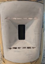
Looks a bit rough with 1mm nozzle. Is this to be expected or can I do way better with this size nozzle? Hopefully it's good enough for testing purposes.
Step 1: if you're using PETG, blast the print with a propane torch, to smooth everything out
Step 2: Use some filler to get a glass finish
Attached is a pic of my latest print. This uses VERY limited sanding. I basically spent ten minutes covering it in that stuff you use to patch drywall, and then ten minutes sanding it.
With some effort, you can get a perfectly smooth finish.
Attachments
Why not start design from here instead?
//
This idea goes back at least 25 years - that's when I first made it. But it's rapid acceptance and implementation shows just how interested manufacturers are in it. Not!
Aren't many CD made with a "front piece" that can be removed and the diaphragm exposed as in the picture?
Do you mean that one cant buy them as such and it implies that one has to throw away a piece of metal? Or what kind of engagement from manufacturers did you have in mind?
//
Do you mean that one cant buy them as such and it implies that one has to throw away a piece of metal? Or what kind of engagement from manufacturers did you have in mind?
//
- Home
- Loudspeakers
- Multi-Way
- Acoustic Horn Design – The Easy Way (Ath4)