Is that correct? I hope so 🙂
I can generate some plots with my python script if you want. I just need the data from the VACS contour plot (Right click on contour plot > Export data...; select "Plain - Text format" and Bode Type "Level dB"; click "Save..."). I'm fairly certain that my math for DI is correct (I used the equations in this paper).
Is it possible to simulate this waveguide on a flat *rectangular* baffle with similar rollback as corner radius? Because it would be really nice to see if this could be integrated with a woofer down below, maybe running as dipole-to-cardioid blend in the bass to midbass region.15" freestanding waveguide, 1" throat. Hmm, it's even better than I anticipated 🙂
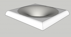
Why would you do that? It would make it worse, not better. Just use it as freestanding, smoothly terminated all around the horn - it can't be any better.
- You have no idea how making it non-symmetric complicates the simulation. It would take maybe 200 - 500x more time to calculate that in a reasonable resolution.
- You have no idea how making it non-symmetric complicates the simulation. It would take maybe 200 - 500x more time to calculate that in a reasonable resolution.
That would be great. The polars attached are 0 - 180 (included) / 5 deg step. There is also the on-axis DI curve.I can generate some plots with my python script if you want. I just need the data from the VACS contour plot (Right click on contour plot > Export data...; select "Plain - Text format" and Bode Type "Level dB"; click "Save..."). I'm fairly certain that my math for DI is correct (I used the equations in this paper).
Attachments
I'd use the woofer as "free standing" as well, maybe with some semi-transparent cover on the back side to attenuate the radiation and form something more like a cardioid (if at all possible) than a pure dipole, as you say. The lower in frequency the crossover would be, the better. I have this in mind for quite a long time. I will probably try this with the 1,4" Faitals.[...] it would be really nice to see if this could be integrated with a woofer down below, maybe running as dipole-to-cardioid blend in the bass to midbass region.
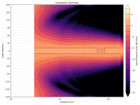
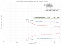
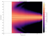
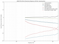
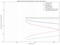
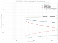
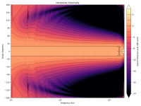
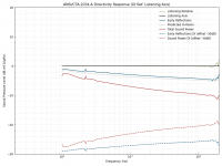
Looks like your DI calculation is accurate (assuming mine is not also wrong in exactly the same way 😉). The graphs are: contour plot, 0° reference (with your DI curve in light grey), 10° reference, and listening window reference.That would be great. The polars attached are 0 - 180 (included) / 5 deg step. There is also the on-axis DI curve.
Attachments
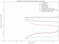

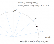
Thanks! This is how I calculate the weights of the polars, BTW. Couldn't be simpler.

Attachments
Last edited:
Is there any smoothing applied to the data? The curves seem a bit more artifact-free than I'd expect based on past experience.
No, I didn't touch it. These are the 100 log-spaced points in the 300 - 20000 Hz range as they come out of the sim.
Hard to believe it, isn't it 🙂
Hard to believe it, isn't it 🙂
Last edited:
Maybe I misunderstood you. If you meant the numeric artefacts, I believe it's because of the high mesh resolution, I also see now that I have NUC activated as default. This is the "CircSym" mode with MeshFrequency=36kHz (which is the value at which I somehow settled but could be easily increased even more).
Last edited:
Yes, I meant the numerical stability problems with CircSym. Back a while ago, I tried increasing the MeshFrequency, but it didn't help much (I think I tried up to 80kHz).
Are you using an interface between interior and exterior subdomains like the half-space sims? Or is everything now in the exterior subdomain? I've been working on getting free-space sims working with my profile generator today and I found that putting everything into the same (exterior) subdomain seems to work fine and gives better results.
Are you using an interface between interior and exterior subdomains like the half-space sims? Or is everything now in the exterior subdomain? I've been working on getting free-space sims working with my profile generator today and I found that putting everything into the same (exterior) subdomain seems to work fine and gives better results.
Last edited:
the model appears to be accurate, please try to find out what model is used.
From ABEC Help File:
The Boundary Element Analysis calculates the acoustic field satisfying boundary conditions, i.e. including reflection and diffraction. The Boundary Element Analysis solves the Helmholtz Integral for the interior and exterior radiation problem [1,2,4,5].
The Boundary Element solver is used here only for the acoustics. Only boundary condition of motion are taken into account. Potential boundary conditions are not supported. The integral is solved by decomposing the structure into triangles assuming constant pressure on each finite element.
Literature
1.Ciskowski, R; Brebbia, C: Boundary Element Methods in Acoustics; Computational Mechanics Publication, Southampton, Boston, 1991; ISBN 0-945824-87-4
2.Brebbia, C; Telles, J; Wrobel, L: Boundary Element Techniques; Springer-Verlag, 1984; ISBN 0-387-12484-5
4.Terai, T: On calculation of sound fields around three dimensional objects by integral equation methods; J. of Sound and Vibration Vol 69 (1) p. 71-100, 1980
5.Seybert, A; et al: A special integral equation formulation for acoustic radiation and scattering for axisymmetric bodies and boundary conditions; JASA Vol 80 (4), Oct 1986
It is all in one exterior domain (not because I think it is the best but because I'm lazy to re-implement all the subdomain interface machinery in the generator). It really works this smoothly for some time now. I noticed as well then but one gets used to that very quickly.
Last edited:
...and now for something bizarre and completely impractical 😀.
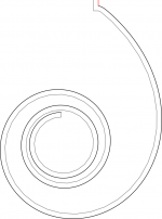
This is huge (36in diameter) with an Euler spiral termination. Evidently, I should have used a higher MeshFrequency (some artifacts above 10kHz).
This is huge (36in diameter) with an Euler spiral termination. Evidently, I should have used a higher MeshFrequency (some artifacts above 10kHz).
Attachments
Last edited:
- Home
- Loudspeakers
- Multi-Way
- Acoustic Horn Design – The Easy Way (Ath4)