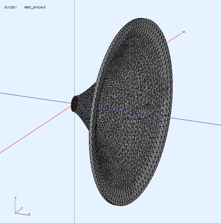
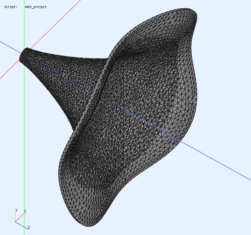
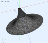
I used a simple method recommended to me by Joerg Panzer (author of ABEC), i.e. utilized a flat (mathematical) surface at the rear side of the waveguide, as if it was flat on the back side. The whole back-side surface of the actual horn could be modeled as well, I just don't consider it practical or very relevant.
Attachments
Last edited:
Nice work! Now you will see that changing the shape of the the edges wil strongly influence te lower part of the spectrum!
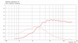
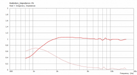
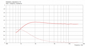
Do I understand it correctly that the fact that the acoustic impedance is still smooth means there is no reflection towards the throat, only diffractions around the edge? Can there be such a thing as diffraction without reflection?
Last edited:
I don't think that there can be diffraction without reflection, but that doesn't mean that the reflections will make it all the way back down the throat. The impedance curve does suggest that there are no reflections reaching the throat.
Based on the few results so far, I think there won't be a need for rolling back of the mouth flare. Which is good news as it looks much better without it, IMHO.
Anything is possible now 
Attachments

Last edited:
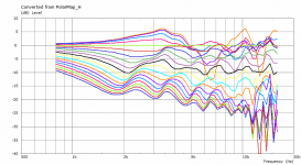
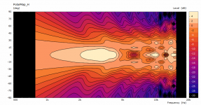
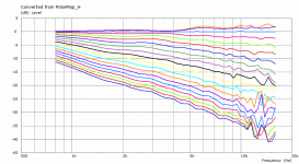
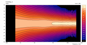
The importance of a proper mouth flare is nicely illustrated in these plots, if we consider the LS50's baffle as a kind of waveguide(extension).
Last edited:
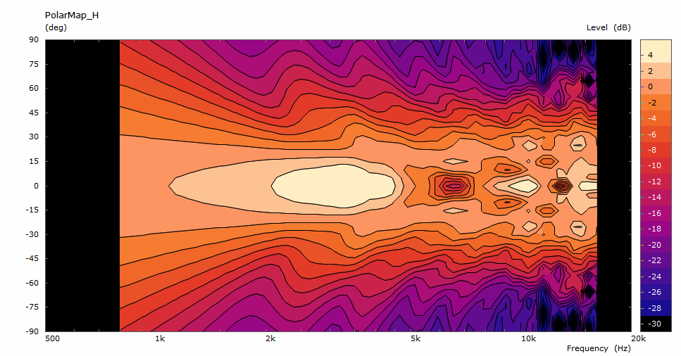
...and something completely different (⌀340 x 200 mm) -
Would a slightly larger mouth (⌀400 x 200 mm) further improve performance?
Last edited:
Try playing with the curve of the flare, you will see that you can taylor the lf directivity with this
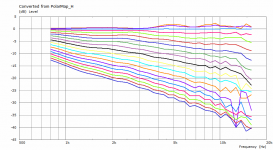
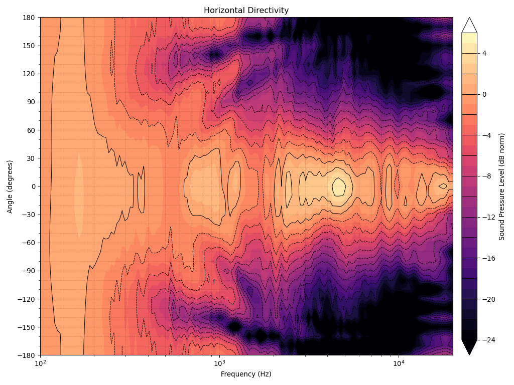
So, I have my first free-standing simulation ever 🙂...
The difference between the infinite baffle and freestanding curves looks to be very similar to the difference in my data:
So it seems that the simulations and reality agree. Obviously the conditions are not exactly the same (freestanding vs cabinet), but the results are similar nonetheless.
Last edited:
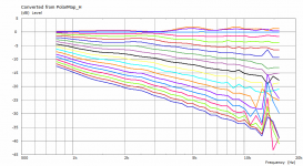
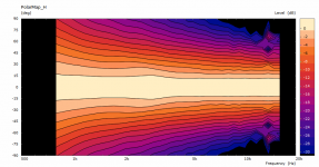
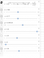
Here you go. Would you consider it "more CD"? I'm not sure I would.If you try something like the attached, you'll see that it will be more cd
It is clear that reducing the flare radius is not a good idea - and this was already too much, IMHO. I could have told you right away but you wouldn't believe me 🙂
Attachments

I have plenty of those 🙂 That would be great. Attached are some designs (full ABEC projects) I would be especially interested in -
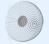
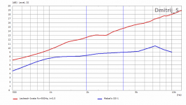
Well, here is a first figure of "full spherical" DI of "OS-1" horn from your uploaded folder. Spatial resolution is 5 degrees. I will try to upload at least one DI graph per day. (sorry for the annoying watermark, but it is added automatically 😀)
I have also depicted DI of this Lecleach-Iwata horn for comparison.
DI rises at the rate of ~2dB/oct for the Lecleach-Iwata horn and a bit less that 1dB/oct for Mabat's "OS-1".
It would be interesting to look at the frequency dependence of random-incidence absorption of a typical listening room. I suppose, that It would be reasonable to optimize horn shape in a such way, that frequency dependence of DI compensate that of room absorption
 .
.Attachments
Last edited:
- Home
- Loudspeakers
- Multi-Way
- Acoustic Horn Design – The Easy Way (Ath4)