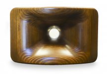
One of the corresponding horns (398 × 250 × 155 mm (W × H × D)) for the driver of # 2556 can be cloned - and improved upon, using ATH4.
Attachments
Last edited:
Unfortunately that's too early to say, it depends on the driver, but even the biggest one should fit in about 105 x 105 x 65 mm (?). I just don't know yet.What are the expected maximum dimensions of the phase plug? I want to buy a resin printer in very near future.
What do you mean by "what was the horn"? This was a predecessor of the Tritonia waveguide I showed the renders of recently. I was actually an accident but worked pretty well. I could still reproduce the shape.
That is some serious effort, what you are doing, Dmitrij.
I mean what was the horn profile ? Was it OS or its modification?
Uh, that's difficult. At the beginning it is OS in every profile, at least for about 1/2 of the length, but as the final step this shape is stretched in the diagonals to form a rectangular mouth outline, so it changes - somewhere it is still exactly OS, somewhere almost OS, somewhere less so... So no, it is not OS (not to mention that a "pure OS" is only axisymmetric).I mean what was the horn profile ? Was it OS or its modification?
No, not at all. It still may be possible with the concave side - if so, it could be easier, provided the original phase plug could be replaced.Is the forward radiating diaphragm concept off the table?
And I really do think the waveguides are done because even if there will be a difference in a finite baffle (and I don't believe it will be a big difference, at least not in +-60° off-axis where all the important happens), you just can't do anything about it - there's just no way how to improve it further, other than make it larger.
This is exactly the same conclusion that I came to over a decade ago. That's when I looked to phase plugs as the only place left for improvement.
Uh, that's difficult. At the beginning it is OS in every profile, at least for about 1/2 of the length, but as the final step this shape is stretched in the diagonals to form a rectangular mouth outline, so it changes - somewhere it is still exactly OS, somewhere almost OS, somewhere less so... So no, it is not OS (not to mention that a "pure OS" is only axisymmetric).
It would be interesting to compare DI of square "AthABECDemo" with any version of pure axisymmetric OS horn. If you have ABEC3 project of axisymmetric OS, you can upload it I will calculate "full sphere" DI.
105x105x65 mm should fit even a small printer, if it would be possible to print it on a side. I have no idea what it means with SLA printers, I only know the demands are different than FDM.
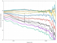
Here's some potentially useful data regarding simulated vs. measured as well as the effect of the cabinet:

This data is from my design (more information here). The grey curves are simulated (infinite baffle), 0° to 80° in 10° intervals. The colorful curves are corresponding measurements of the completed loudspeaker (solid is positive, dashed is negative... obviously I didn't get the 0° axis perfect 😱). The agreement is pretty good out to about 50°, but the measured data shows narrower dispersion beyond that, especially below 2-3kHz. I'm guessing that this is due to the diffraction around the cabinet. So, it appears that the cabinet actually improves the directivity vs an infinite baffle 😀.
This data is from my design (more information here). The grey curves are simulated (infinite baffle), 0° to 80° in 10° intervals. The colorful curves are corresponding measurements of the completed loudspeaker (solid is positive, dashed is negative... obviously I didn't get the 0° axis perfect 😱). The agreement is pretty good out to about 50°, but the measured data shows narrower dispersion beyond that, especially below 2-3kHz. I'm guessing that this is due to the diffraction around the cabinet. So, it appears that the cabinet actually improves the directivity vs an infinite baffle 😀.
Attachments
Well, there is still one feature to be introduced, as I already announced before - free-standing, free-form waveguides, which will open a whole new world of possible shapes and outcomes. I only don't really believe it will bring much of an improvement to what we already have, what is meant to be used in a (rounded) box - a finite baffle.
Of course I haven't forgotten the free-standing variant, because that's exactly what I'm after

Last edited:
This data is from my design (more information here). The grey curves are simulated (infinite baffle), 0° to 80° in 10° intervals. The colorful curves are corresponding measurements of the completed loudspeaker (solid is positive, dashed is negative... obviously I didn't get the 0° axis perfect 😱). The agreement is pretty good out to about 50°, but the measured data shows narrower dispersion beyond that, especially below 2-3kHz. I'm guessing that this is due to the diffraction around the cabinet. So, it appears that the cabinet actually improves the directivity vs an infinite baffle 😀.
Wonderful example, thank you so much. It's so good to see this kind of study. Bravo!
Thanks, this is something I wondered about a lot and hoped this would be the case. And indeed, it is 🙂...The agreement is pretty good out to about 50°, but the measured data shows narrower dispersion beyond that, especially below 2-3kHz. I'm guessing that this is due to the diffraction around the cabinet. So, it appears that the cabinet actually improves the directivity vs an infinite baffle 😀.
Thanks, Dr. Geddes. I couldn't have done it without your (and mabat's) contributions to this forum.
Here's another plot that should be a little easier to interpret:

The original plot had the simulated data normalized to the design axis (18°), but the measured data was not normalized. Here I've normalized both data sets to the same angle.
Here's another plot that should be a little easier to interpret:
The original plot had the simulated data normalized to the design axis (18°), but the measured data was not normalized. Here I've normalized both data sets to the same angle.
Attachments

bmc0, thanks for the plots.
It is interesting to see that the roundovers apparently have little effect.
I wonder about the approximate ideal diameter of an axisymmetrical waveguide for a 1" driver and an estimated crossover between 700 and 800Hz. Apart from 'infinite' 😀
It is interesting to see that the roundovers apparently have little effect.
I wonder about the approximate ideal diameter of an axisymmetrical waveguide for a 1" driver and an estimated crossover between 700 and 800Hz. Apart from 'infinite' 😀
Last edited:
It is interesting to see the roundovers apparently have little effect.
Not sure what you mean by this. I don't have data for the same waveguide in a sharp-edged box, so I don't know how you could determine the effect of the roundovers.
The agreement is pretty good out to about 50°, but the measured data shows narrower dispersion beyond that, especially below 2-3kHz. I'm guessing that this is due to the diffraction around the cabinet. So, it appears that the cabinet actually improves the directivity vs an infinite baffle 😀.
After owning the Gedlee Summas for about eight years, I came to the conclusion that the cabinet was possibly the most important part of the speaker. Most people focus on the waveguide and the foam club but I think that cabinet is really special.
I've spent way too much time poring over polar maps, and I think what happens is that you get a sloooow transition from:
1) radiation that's defined by the angle of the waveguide
2) radiation that's defined by the dimensions of the loudspeaker baffle
3) radiation that's defined by the dimensions of the cabinet
For instance, most of our sims are based on an infinite baffle (1). With an infinite baffle, the output is always radiating into 180 degrees when the wavelengths are longer than the waveguide diameter. This means that if you have a 12" waveguide, 1500Hz will be constrained by the waveguide dimensions, but 750Hz will be constrained by the baffle.
IE, if you had a 90 degree waveguide and an infinite baffle, you'd get a transition from 90 degrees to 180 degrees at around 1125Hz.
I think what happens with a carefully designed baffle and enclosure, is that you can extend the directivity control much lower than normal.

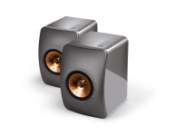
For instance, here's the polars of the Kef LS50. It's waveguide is only six inches in diameter. Based on that, you'd expect it's directivity to collapse around 2khz.
But it doesn't - it has narrowed directivity down to 750Hz.
And I think this is because of the baffle. Basically you have a finite amount of energy being radiated. And if you juggle the height, width, depth and curvature of the baffle, you can extend the directivity control.
This is because the energy that's radiated isn't being radiated into 180 degrees (like a flat baffle) but it's not radiated into 360 degrees either (like an omnipole.)
It's somewhere in between, and that's making it look as if the LS50 is using a 15" diameter waveguide, when it's actually just 6".
Not sure what you mean by this. I don't have data for the same waveguide in a sharp-edged box, so I don't know how you could determine the effect of the roundovers.
The real effect cannot be determined without a sharp-edged comparison cab, true.
However, basic acoustics implies that towards the low end of the spectrum the wavelengths won't even 'see' the roundovers of your cabs (1000 Hz = 13.56 Inches).
Last edited:
The real effect cannot be determined without a sharp-edged comparison cab, true.
However, basic acoustics implies that towards the low end of the spectrum the wavelengths won't even 'see' the roundovers of your cabs (1000 Hz = 13.56 Inches).
I did some research into that, and that was my experience too. Basically a roundover on a small cabinet with a small waveguide make the beamwidth wider. A roundover on a cabinet with a large waveguide did virtually nothing.
I think this is because of two things:
1) the wavefront is radiating into a narrower angle. IE, because it can't 'wrap around' the baffle, more energy is going FORWARD, and due to that, the on axis response is louder. Which manifests itself as wider beamwidth.
2) I think sharp edges can create secondary sources, and those secondary sources can narrow the beamwidth on a box with sharp edges, due to destructive intererence from the diffraction off the sharp edges.
See : What Do Roundovers Do?
For instance, here's the polars of the Kef LS50. It's waveguide is only six inches in diameter. Based on that, you'd expect it's directivity to collapse around 2khz.
But it doesn't - it has narrowed directivity down to 750Hz.
And I think this is because of the baffle. Basically you have a finite amount of energy being radiated. And if you juggle the height, width, depth and curvature of the baffle, you can extend the directivity control.
This is because the energy that's radiated isn't being radiated into 180 degrees (like a flat baffle) but it's not radiated into 360 degrees either (like an omnipole.)
It's somewhere in between, and that's making it look as if the LS50 is using a 15" diameter waveguide, when it's actually just 6".
The curved baffle is undoubtedly effective and the final design probably required quite a few simulation hours.
Attachments
Last edited:
- Home
- Loudspeakers
- Multi-Way
- Acoustic Horn Design – The Easy Way (Ath4)