As for 'wide coverage' constant directivity over long distances with a single horn, I think this can only be accomplished by going the Danley route, i.e. multiple compression drivers to compensate for the falling response.
But what about in home hifi... We most need 2.5 meters to 5 meters fro the speakers. I surmise most are in this scenario, few below, very few above...
John Patrick Batemann has a good experience from the readings : shoert listening distance and experienced genuine Gedles speakers, Danleys, and several diy hoen if I remember crrectly what I have read.
Is the listening distance important for the horn profile ? I.E. related to PA world instead : short listening distances ?
Last edited:
According to Toole:
Directivity index (DI).
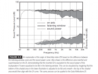
Traditional DI is defined as the difference between the on-axis curve and the normalized sound-power curve. It is thus a measure of the degree of forward bias—directivity—in the sound radiated by the loudspeaker. It was decided to depart from this convention because it is often found that, because of symmetry in the layout of transducers on baffles, the on-axis frequency response contains acoustical interference artifacts, due to diffraction, that do not appear in any other measurement. It seems fundamentally wrong to burden the directivity index with irregularities that can have no consequential effects in real listening circumstances.
Therefore, the DI has been redefined as the difference between the listening window curve and the sound power. In most loudspeakers the difference is small; in highly directional systems it can be significant. In any event, for the curious, the raw evidence for the classic DI is there to inspect. Obviously, a DI of 0 dB indicates omnidirectional radiation. The larger the DI, the more directional the loudspeaker in the direction of the reference axis. This is illustrated in Figure 5.9. Because of the special importance of early reflections in what is measured and heard in rooms, a second DI is calculated, the Early Reflections DI, which is the difference between the listening window curve and the early-reflections curve. Because of the importance of early reflections in common sound reproduction venues, this is arguably the more important metric.
All of this is summarized in Figure 5.6.
Directivity index (DI).
Traditional DI is defined as the difference between the on-axis curve and the normalized sound-power curve. It is thus a measure of the degree of forward bias—directivity—in the sound radiated by the loudspeaker. It was decided to depart from this convention because it is often found that, because of symmetry in the layout of transducers on baffles, the on-axis frequency response contains acoustical interference artifacts, due to diffraction, that do not appear in any other measurement. It seems fundamentally wrong to burden the directivity index with irregularities that can have no consequential effects in real listening circumstances.
Therefore, the DI has been redefined as the difference between the listening window curve and the sound power. In most loudspeakers the difference is small; in highly directional systems it can be significant. In any event, for the curious, the raw evidence for the classic DI is there to inspect. Obviously, a DI of 0 dB indicates omnidirectional radiation. The larger the DI, the more directional the loudspeaker in the direction of the reference axis. This is illustrated in Figure 5.9. Because of the special importance of early reflections in what is measured and heard in rooms, a second DI is calculated, the Early Reflections DI, which is the difference between the listening window curve and the early-reflections curve. Because of the importance of early reflections in common sound reproduction venues, this is arguably the more important metric.
All of this is summarized in Figure 5.6.
Attachments
Last edited:
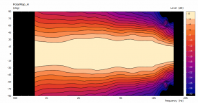
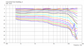
Out of curiosity I've tried the Tritonia waveguide freestanding - just the bare waveguide (1,4" throat):
Attachments
Last edited:
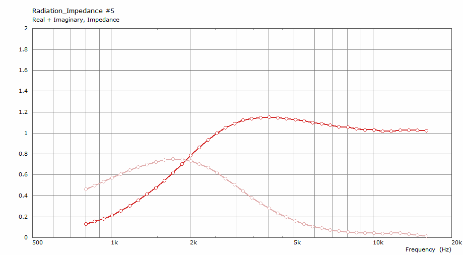
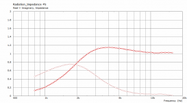
The impedance is still without a hint of reflection which is what strikes me the most. I almost have doubts if I set up the simulation properly. Either I do something wrong or are doing so all the guys with those terribly wavy impedance curves... 🙂
Can't wait to see it measured in an enclosure.
Can't wait to see it measured in an enclosure.
Attachments
Last edited:
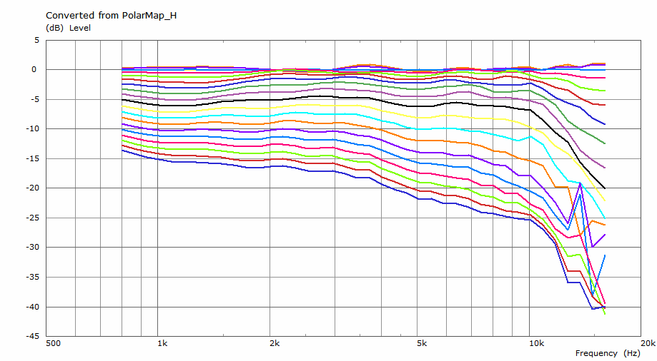
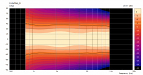
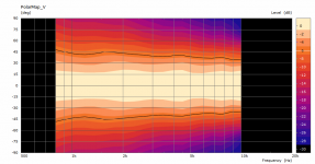
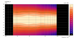
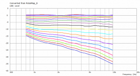
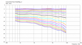
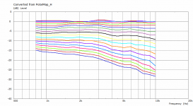
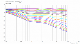
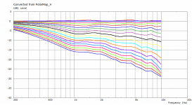
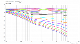
Made a little longer (180 mm) with coverage more like 85° (the previous was wider, around 100°).
Horizontally, vertically and diagonally - the DI would be pretty flat in this case.
Horizontally, vertically and diagonally - the DI would be pretty flat in this case.
Attachments
Last edited:
Not yet. I'm actually thinking about going axisymmetric for now as the fabrication would be tremendously easier.
We still know less how you realized the free-standing calculations. Would you please show obervation fields for one of your free-standing calculations that we are able to assess what's going on inside and outside the horn.
The Phase-Plug
As I would consider waveguides basically done by now, the next goal is really the phase plug providing a spherical wave, improving the last octave (or so). Although I have already expressed my concerns about the real merit, it would certainly be exciting to have it. I just can't make the whole project on my own - I can prepare all the design tools for simulation but the actual fabrication is out of my reach at the moment (I'm thinking about SLA prints). Would there be anyone equipped and willing to participate in such a project?
As a CNC-operator (in the wood industry), I could produce molds for casting: Although you can machine the small parts directly from stock material, it tends to require complex fixtures and multiple processes. A two part mold on the other hand is simple. I have some high density foam (Sica block, which i believe is made from filled epoxy), which I think will do fine with the right release agent. I'm not setup for machining metal molds. Perhaps Earl can recommend a casting material? two part polyurethane? epoxy?
STL, Solids or surface files are all fine file formats. I even think Fusion 360 has an automatic mold making feature, which makes the two mold parts from the master, given some few other constrains.
- Home
- Loudspeakers
- Multi-Way
- Acoustic Horn Design – The Easy Way (Ath4)