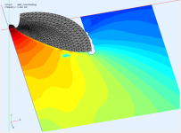
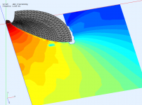
Yet another explanation: Imagine that the interior of the waveguide is completely hidden to you and the whole device is represented by a surface across the mouth - a virtual source with exactly the same properties as the soundwaves emanating from inside the waveguide. Make this surface a front side of a very short cylinder (5 mm in this case) and you have a pretty good approximation of a free standing device, with all the diffration around the egde. This is exactly how it can be done in ABEC, it's called sub-domain modeling.
Last edited:
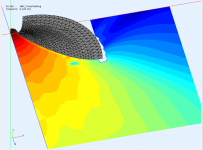
Well it does display the intensity along an arc
Is the plot truly intensity? You said earlier that it was SPL. The two are not the same. I'd love to see a plot of intensity flow in the waveguide.
Sorry, my bad, it is SPL and as far as I know it is the only quantity possible to visualize this way.
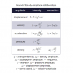
Thinking about this, I could make as many pressure probes inside the waveguide as needed for a special post-processing. I'm only not sure the pressure gradient itself would be sufficient to calculate the intensities (?). The visualization could be handled in some other software easily.
Yet another explanation: Imagine that the interior of the waveguide is completely hidden to you and the whole device is represented by a surface across the mouth - a virtual source with exactly the same properties as the soundwaves emanating from inside the waveguide. Make this surface a front side of a very short cylinder (5 mm in this case) and you have a pretty good approximation of a free standing device, with all the diffration around the egde. This is exactly how it can be done in ABEC, it's called sub-domain modeling.
This is true, but you will still need to model the enclosure, this can be another sub domain
The easiest way is to connect a lot of edgepoints to a single point at a small distance behind the throat
Last edited:
Why should I need to model an enclosure if I want to simulate a bare free standing waveguide?
For a waveguide in an enclosure, sure. I'm working on that, it's just a small extension of what I have.
For a waveguide in an enclosure, sure. I'm working on that, it's just a small extension of what I have.


These are the corresponding far-field polars. It is 2x45 deg nominal coverage (the black line) so I'd say it's just about right (?).
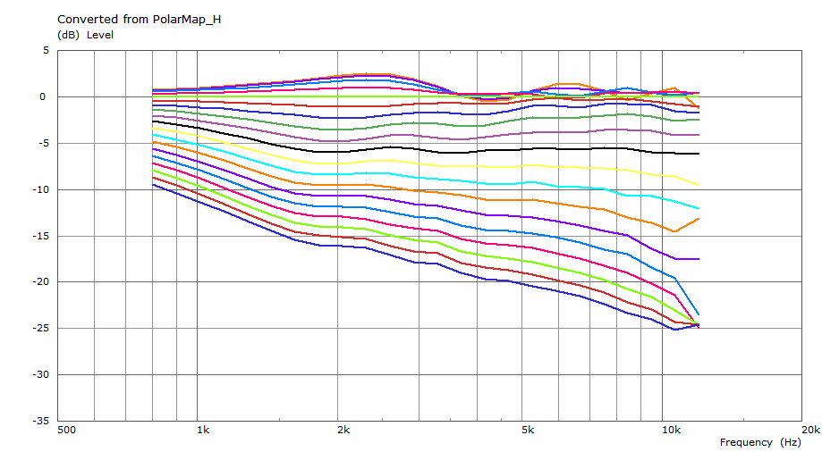
It does seem just about right.
Is this axisymmetric bat1?
Do you know what puzzles me? When I make the free standing cylinder longer (50 mm here), it is actually worse. This seems counter-intuitive to me...

It looks like some diffraction settles in, which given de diameter, isn't surprising.
At ⌀400 these ripples should be reduced.
A roundover (ugly I know) might also help.
Last edited:
No, these are is still variations on the demo project - ⌀300 x 100 mm axisymmtric waveguide with 1" throat.
Maybe the above are just some numerical problems, I don't know. It's hard for me to believe that longer cylinder would be worse. Or could the two more separated diffraction points cause this?
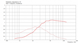
The plots would indicate that more energy is actually reflected back down the throat. Like if there would be a stronger impedance mismatch at the first edge (maybe caused by the second edge?).
Maybe the above are just some numerical problems, I don't know. It's hard for me to believe that longer cylinder would be worse. Or could the two more separated diffraction points cause this?
The plots would indicate that more energy is actually reflected back down the throat. Like if there would be a stronger impedance mismatch at the first edge (maybe caused by the second edge?).
Last edited:
Thinking about this, I could make as many pressure probes inside the waveguide as needed for a special post-processing. I'm only not sure the pressure gradient itself would be sufficient to calculate the intensities (?). The visualization could be handled in some other software easily.
If you have the pressures at two parallel surfaces that are either spherical or flat then the gradient is fine, it's just has to be done in the coordinate system of the surface. The radial gradient in the case of a sphere.
Thanks, I may try that.
Just to be clear the intensity is the velocity times the complex conjugate of the pressure (or the other way around, don't remember.) The pressure is the sum of the pressures on the two planes (over 2) and the velocity is the gradient (in cartesian it's the differences of the pressures.) This gives the intensity in the middle of the planes. There can also be a component parallel to the planes which should also be calculated and added to the normal intensity.

I think you may be missing the point here. The diameter didn't change, it's 300 mm all the time. What changed is the depth (length) of the cylinder in which this waveguide was put into for a free standing simulation - 5 and 50 mm. The first one is just fine (what you thought to be the 'bat'), the second is noticeably worse......It looks like some diffraction settles in, which given de diameter, isn't surprising. At ⌀400 these ripples should be reduced.
A roundover (ugly I know) might also help.
This would mean, BTW, that if you were building an open baffle, you'd better make it as thin as possible (or rounded?)
Somewhere on a French forum, I read an interesting analysis from an Acoustical Engineer about driver interface vs path length vs horn-mouth vs baffle.
The math was way above my head, but it made clear why, for example, the 18Sound XT1464 is better than the shorter XR14 .. horns.
The math was way above my head, but it made clear why, for example, the 18Sound XT1464 is better than the shorter XR14 .. horns.
Last edited:
Yet another explanation: Imagine that the interior of the waveguide is completely hidden to you and the whole device is represented by a surface across the mouth - a virtual source with exactly the same properties as the soundwaves emanating from inside the waveguide. Make this surface a front side of a very short cylinder (5 mm in this case) and you have a pretty good approximation of a free standing device, with all the diffration around the egde. This is exactly how it can be done in ABEC, it's called sub-domain modeling.
Thanks for posting the method. That was not obvious at first but it makes sense as to why it allows radiation from the horn. They are coupled via the subdomain interface even though they (horn interior and exterior) physically intersect.
However, the horn exterior is now modeled as a simple cylinder and that is just an approximation of the real exterior. Changing the cylinder width changes the results. Just like changing the mouth subdomain interface shape effects the results. Interestingly, with this method, the inside of the horn is bigger (volume) than the outside 🙂
Last edited:
- Home
- Loudspeakers
- Multi-Way
- Acoustic Horn Design – The Easy Way (Ath4)