I did some analysis and found that this doesn't work as expected. What I found is that the radiation patterns really should match at the crossover frequency, horizontally AND vertically, otherwise you won't achieve smooth power response transition.
Can you explain how you did this analysis? Or is it available so I can study it?
I am surprised that you found the radiation patterns should match the same both horizontally AND vertically.
The need to horizontal match looks obvious.
(This assumes a vertically stacked woofer and horn, and that we measure on the plane equidistant from the two sources so they stay in fixed phase relation.)
But the physical situation is quite different in the vertical plane, the two sources are separated so the phase varies in a classic interference set up.
With such different physics I would expect the optimum solution would almost surely be different.
I am also a little surprised you mention the "power response".
For 2nd or more order crossover and non coincident sources we usually can't have both flat on axis and flat power summation, can we?
I follow the Harman research and aim for flat across the listener window, in accordance with CTA 2034.
Moreover, it is not necessarily true...But take this only as my observation as I don't claim this to be universally true - it's still only a somewhat "random" observation, really.
I respect your observation, and Earl's, perhaps I will come to the same conclusion.
But I haven't seen or formulated any universally true "laws" either.
So I know no conservation law that says there has to be trade-off for better vertical performance.
I don't plan to narrow the horn vertically to move the sources closer, I am in accord with you that this is counterproductive.
I may push the woofer up into the horn mouth, like bmc0 has done, perhaps somewhat more.
If not overdone the reduced separation should improve the polar response with minimal impact from the small discontinuity.
Elliptical...dimensions 740 x 550 x 300 (W x H x D) ~ 29.1" x 21.5" x 11.8", throat 36 mm (1.4").
There will be a pattern flip around 1 kHz.
Thank you for that, it will make an excellent benchmark to compare with my own efforts.
Nice to have more realistic data to confirm my rule of thumb estimate that a horn that size would have pattern flip around 1 kHz.
The idea is that 1kHz is about where the woofer would start to cut in.
So the broader combined vertical source would then help to maintain pattern control down to the crossover frequency of around 650 or 700 Hz.
It really needs a proper simulation of woofer plus horn.
Should be doable but maybe by someone more enthusiastic than me.
Other option is old fashioned "cut and try" 'til I'm satisfied.
Hence my interest in hot wire cut foam as a rapid prototype system.
Pity no one else was interested.
Best wishes
David
Last edited:
If directivity files in 10 degree steps (or better) can be exported from the tools, they can be used in a Vituix crossover simulation that will yield polar maps of the combined horn+woofer system with little extra effort. If file export isn't possible but frequency response plots are at multiple angles, the Vituix SPL trace program works very well.
can be exported from the tools, they can be used in a Vituix crossover simulation that will yield polar maps of the combined horn+woofer system with little extra effort...the Vituix SPL trace program works very well.
Thank you, that seems like an excellent way to save a lot of work compared to a full ABEC simulation.
Best wishes
David
Exactly as ns535 suggests, I generated polar data for the two sources, loaded them into a simulator (not exactly VituixCAD as I still use my own, but that's beside the point) and tried different scenarios. I don't remember all the details, all I can say is that the best results were for the two radiation patterns being really the same, for 3rd order filters acoustically (phases in quadrature across the overlap for the direct sound) and it was certainly possible to achieve flat direct sound and the power response.
Last edited:
... tried different scenarios. I don't remember all the details, all I can say is that the best results were for the two radiation patterns being really the same, for 3rd order filters acoustically (phases in quadrature across the overlap for the direct sound)...
OK, makes sense, I haven't explored phase quadrature crossovers much.
I have mostly tried 4th order (in phase), on the premise that there's already usually a 2nd order acoustic roll-off so by the time we add a moderate electronic roll-off we are at 4th order.
So many possibilities...
Best wishes
David
I may push the woofer up into the horn mouth, like bmc0 has done, perhaps somewhat more.
I did this as well on the NA12. It was a small improvement, but nothing major. As the woofer gets pushed more and more into the waveguide, diffractions and reflections begin to take a toll. A small amount works fine, but too much is bad.
I did this as well on the NA12....A small amount works fine, but too much is bad.
Yes, that is, as previously noted, what I expect.
So how did you determine the amount to push- simulation, experiment or "eyeball" it?
Any reason to do it on the NA12 but not Summa?
What (acoustic) crossover order?
Best wishes
David
The NA12 is the Summa 18" waveguide in an Abbey cabinet. This meant that the waveguide overlapped the edges as well as the woofer. The location was fixed by where the waveguide had to go to fit into the existing molds.
I have never really worried about crossover "orders", but I guess you would say that the LP is usually third, but I have also use a second order here as well, and the HP is third (acoustically.)
I have never really worried about crossover "orders", but I guess you would say that the LP is usually third, but I have also use a second order here as well, and the HP is third (acoustically.)
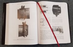
Maybe you ready know this article ? https://www.grc.com/acoustics/An-Introduction-to-Horn-Theory.pdf
Attachments

The NA12 is the Summa 18" waveguide in an Abbey cabinet. This meant that the waveguide overlapped the edges as well as the woofer. The location was fixed by where the waveguide had to go to fit into the existing molds.
I have never really worried about crossover "orders", but I guess you would say that the LP is usually third, but I have also use a second order here as well, and the HP is third (acoustically.)
Earl, having made and measured both a 18" and a 12" waveguide in the same baffle, can you elaborate on the tradeoffs involved? How much off an issue is the diffraction of the Na12 really? How much is gained in terms of directivity? Looking at the polars, it doesn't have the waistbanding one might expect..
The 18" holds its control to a lower frequency which allows for a lower crossover point and a higher DI across the board. (You may see this as "waistbanding".) This is not readily apparent in the plots (unless you compare the DI directly.) Diffraction at the mouth is negligible in the 18" but is more significant in the 12". This is mostly due to the 18" having a larger radius flare at the mouth.
That was something that wasn't readily apparent to me - though now it seems obvious:
Basically the cabinet itself doesn't necessarily need a roundover with a large waveguide.
IE, I'd always assumed that ALL loudspeaker cabinets should have a roundover, it was just a no-brainer. But measuring a bunch of speakers, I realized that you can eliminate the roundover IF the waveguide is sufficiently large:
What Do Roundovers Do?
I've always wondered that myself. The woofer will still diffract from the edges, especially if it goes way up to 1 kHz (which neither the NA12 or the NS15 do.) So you may be right that roundovers might not be such a big deal with a well controlled waveguide. I just never tried anything without them. It just seems like it is always a "good" idea.
No need for roundovers on the baffle IMO (unless the baffle is completely curved), especially with a target XO around 700Hz.
A freestanding axisymmetric 80° waveguide (± 20" diameter) overhanging the woofer (surround) shouldn't be problematic.
In this case, it seems useful to round off the edges of the waveguide.
A freestanding axisymmetric 80° waveguide (± 20" diameter) overhanging the woofer (surround) shouldn't be problematic.
In this case, it seems useful to round off the edges of the waveguide.
Last edited:
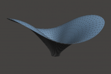
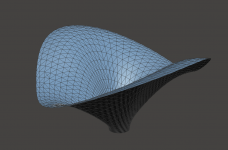
You want it, you got it - 🙂
Length = 100+30*sin(2*p) ; [mm]

Length = 100+30*sin(2*p) ; [mm]
Attachments
Last edited:
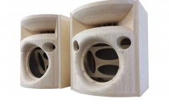
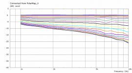
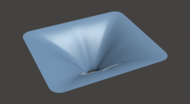
The latest iteration of my best rectangular design -
Dimensions: 374 x 324 x 120 mm
Throat: 1,4"
(Angular step is 5°, so the black line in the middle corresponds to 45° off-axis)
Dimensions: 374 x 324 x 120 mm
Throat: 1,4"
(Angular step is 5°, so the black line in the middle corresponds to 45° off-axis)
Attachments


Last edited:
Marcel, will you share it slightly bigger approx. 49x45cm? I currently run test print of that big using 0.8mm nozzle, 0.6mm layer: 35 hours.
- Home
- Loudspeakers
- Multi-Way
- Acoustic Horn Design – The Easy Way (Ath4)