Hello,
Sorry to ask due to the high levels of inputs.
What mouth width and deepness and shape would have your preference for a 7.5 cm throat to load a 3" cone driver from a 800 hz electrical XO, so not a muscled compression driver, please.
I hesitate on the mouth and OS shape to marry to a 15" driver at 800 hz...
Many thanks for your thoughts here... the 3" needs spl load as it is a 87 db...
Last edited:
I have no experience with this kind of design so I can't really help. Moreover, the whole concept of "loading" is still somewhat mysterious to me. But I suspect you would need a phase plug first. It might be interesting to hear what others think.
"loading" aside, I would expect a directly radiating 3" driver to work well on a waveguide up until about 2-3 kHz, at which time things will get messy. That's because the much lower cut-in of the HOMs will become excited by the decidedly non-flat wavefront of the driver causing a serious disruption of the response. A phase plug could extend this several more kHz, but getting to 10-20 kHz is never going to happen with a diver with such a weak force factor (86 dB.)
Thanks gentlemen for the inputs.
Loading in my simple understanding is about spl increase as directivity is the cunterpart. I understand almost nothing (or at least I think it's the opositt if I understand some few inputs : loading i a consequence of the main physical factor which is directivity given by the WG shape... two sides of same coins for my basic understanding).
The driver is the Scan Speak 10F/8424G00, sort of full range from 500/700 hz (H3 is low above 750 Hz). Btw I had also helps of another gentleman who is Joseph Crowe, but the task is harder I was thinking for my understanding... Fascinating are the horn/WG I would say 'and the bells since antic times as well which are sort of horns but that is another story). No idea of the angle degree of this cone... and cone beinga mini horn, i"m lost.
The unknown factor is if a cone that is less stif than a CD diaghpragm is keeping its linearity with a horn 'CD are less flat idea, just don't know how much important it is with the trade off... I see all of you are always talking about copression drivers from 1" to 2"... but in the case one don"t need PA spl or low wattage amp, cone or hifi dome could be an alternative - well highly imputed with tweeter domes as you know-
Thanks for this thread, really fascinating.
Last edited:
Well, I once put this Peerless 2" driver into a 10" Dayton waveguide (cut-off). It was not quite what I hoped for but this was just a single random experiment, based on which I can't make any conclusions. A waveguide in general would help to unify the directivity pattern, i.e. to increase the DI at lower frequencies. That alone would be beneficial. I suppose you could use Ath calculator for this, just use 3" throat and a piston source, I'd opt for a shallow smooth waveguide and probably not OS - more like conical with a larger initial angle (just guessing). For lower frequecies this should be pretty close. The rest will be given by the details of the particular real-world diaphragm which are completely different animal to simulate and Ath can't do this. You would have to wait and measure what you get...
Last edited:
Thank you so much mabat, appreciated.
I list all the answers given here and elsewhere to try to make something 🙂.
I list all the answers given here and elsewhere to try to make something 🙂.
Hello Mabat,
Horn/Waveguide application of the 50 mm/2" Peerless has been on my mind for some years now. Would some kind of a phase plug improve the situation?
Maybe a question that Patrick Bateman might answer?
Horn/Waveguide application of the 50 mm/2" Peerless has been on my mind for some years now. Would some kind of a phase plug improve the situation?
Maybe a question that Patrick Bateman might answer?
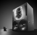
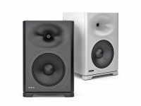
Example of waveguide-loaded midwoofers; Genelec 1236A
Brief technical specifiations:
Sound pressure level: 130 dB
Free field system frequency response: 17 Hz – 26 kHz (-6 dB)
Accuracy of frequency response: +/- 2 dB (21 Hz – 20 kHz)
Crossovers: 400 Hz and 3.2 kHz
Drivers: 2x woofers 18 in (458 mm), 2x midrange 5 in (125 mm), tweeter 2 in (50 mm) compression driver + DCW.
Attachments
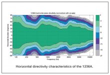
DCW™ stands for Directivity Control Waveguide Technology.
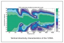
Obviously, a single large ATH4 would easily beat the polars of the 1236A, especially in the vertical plane.
Moral of the story: it's not easy to hornload vertically stacked woofers and get decent results, even more so if these are bigger than about 2".
Obviously, a single large ATH4 would easily beat the polars of the 1236A, especially in the vertical plane.
Moral of the story: it's not easy to hornload vertically stacked woofers and get decent results, even more so if these are bigger than about 2".
Last edited:
WOW that genelec looks so much worse than I ever would have imagined. not even very constant in the horizontal plane. looks like the S360 is a huge step up from this kind of thing.
The S360's polars are better, true.
Price/performance ratio, while not necessarily bad, could easily be bettered by DIY.
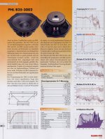
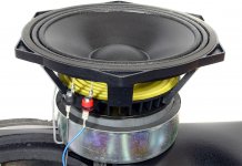
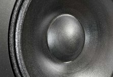
The woofer in the S360 is an OEM version of the PHL Audio 3002.
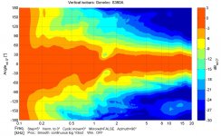
Here's a German review of the S360, including measurement data.
Price/performance ratio, while not necessarily bad, could easily be bettered by DIY.
The woofer in the S360 is an OEM version of the PHL Audio 3002.
Here's a German review of the S360, including measurement data.
Attachments
-
 kt_test_phl_3002.jpg427.8 KB · Views: 229
 -
 genelec-s360-woofer2.jpg108.6 KB · Views: 560
 -
 genelec-s360-woofer1.jpg150 KB · Views: 488
 -
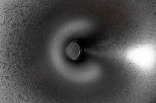 genelec-s360-waveguide1.jpg120.3 KB · Views: 519
 -
 S360_Plots.jpg337 KB · Views: 446
 -
Designing the new Genelec S360.pdf1.2 MB · Views: 173
-
 20190206011243_Genelec-s360-set-Web.jpg457.9 KB · Views: 465
Last edited:
It's quite remarkable to observe that bmc0's big axisymmetrical waveguide + 12" woofer, don't yield (much) worse nulls around the crossover point, compared to the tiny elliptical wg + 10" woofer of the S360.
Last edited:
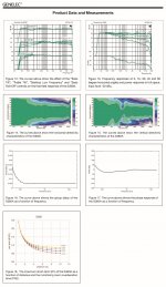
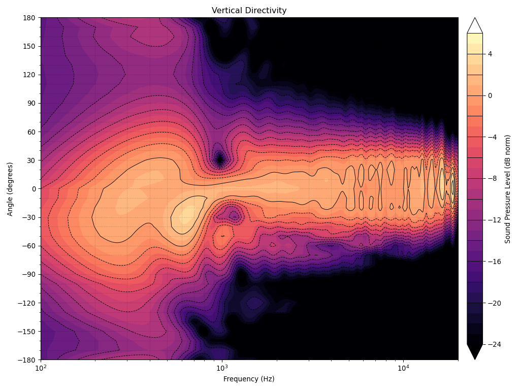
Vertical directivity of the S360, as measured by Sound and Recording:
Attachments
Last edited:
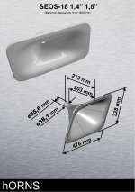
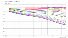
I have been experimenting with rectangular shapes for the last few weeks, incorporating some new features, and this is the result -
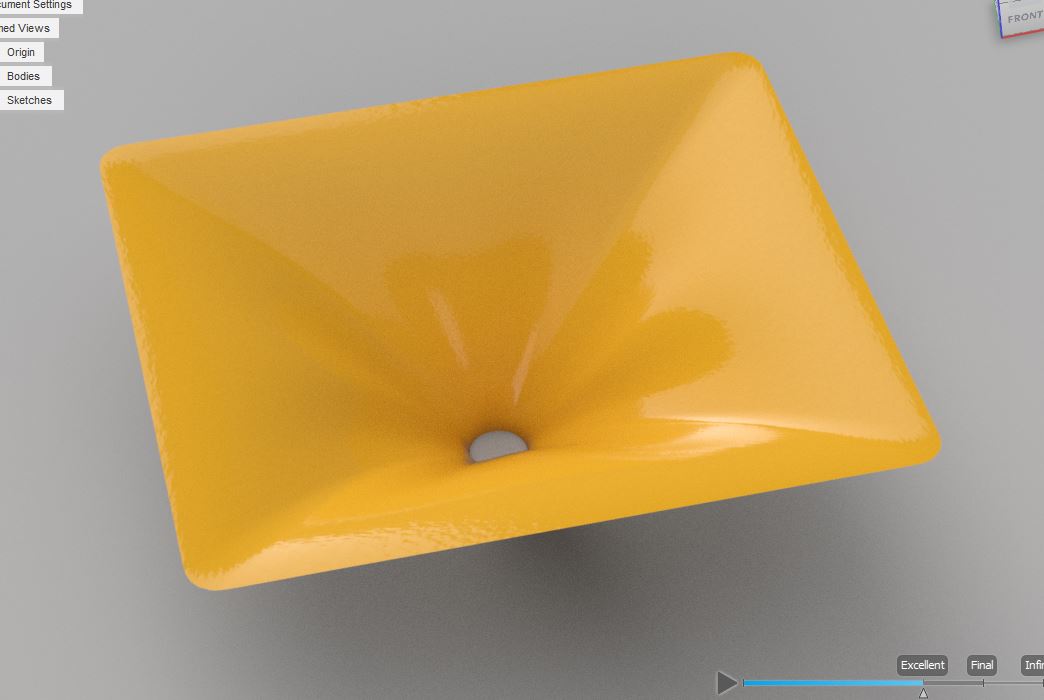
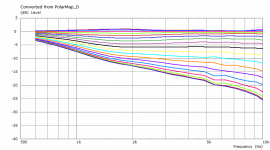
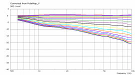
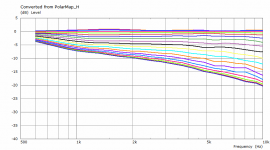
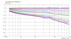
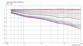
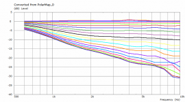
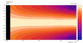
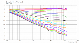
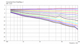
Horizontal, vertical and diagonal simulations (infinite baffle) attached, 0 - 90° per 5°. I'd say this is about as good as it gets. This particular one is 422 x 364 x 135 mm, intended to be used with 18sound ND3T from about 700 Hz.
Horizontal, vertical and diagonal simulations (infinite baffle) attached, 0 - 90° per 5°. I'd say this is about as good as it gets. This particular one is 422 x 364 x 135 mm, intended to be used with 18sound ND3T from about 700 Hz.
Attachments
The same geometry, mainly deeper, now 468 x 396 x 180 mm. Comparison of radiation impedances on the 4th picture.
(Again, the black line in the middle is 45° off-axis).
(Again, the black line in the middle is 45° off-axis).
Attachments

Last edited:
I like the horns. Wondering if MTM would be an improvement....
How would an MTM arrangement impact the vertical directivity? Would the pinching at 1Khz be less pronounced?
How would an MTM arrangement impact the vertical directivity? Would the pinching at 1Khz be less pronounced?
Still a deeper one, 488 x 406 x 220 mm.
(Only a coarse mesh, solved in 30 minutes.)
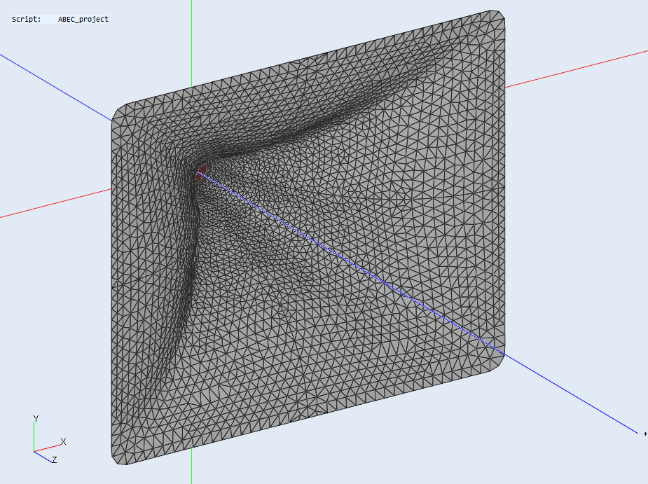
(Only a coarse mesh, solved in 30 minutes.)
Attachments


- Home
- Loudspeakers
- Multi-Way
- Acoustic Horn Design – The Easy Way (Ath4)