That is a fairly complex set of parameters from the looks of it. Very gradiual mouth curve horizontally, and quick transition from round to rectanggular. And the dimensions? - I thought you where all about flat(ish) DI waveguides (same vertical/horizontal directivity)?
Actually, I think the DI will be pretty flat, at least for the first one shown (the widest beamwidth). This is still something I need to implement and show in VACS - the DI curve. From the polars I'd say it shouldn't be much different horizontally and vertically either. There's a difference but not a huge one.
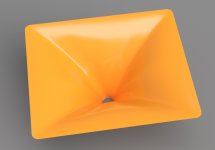
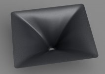
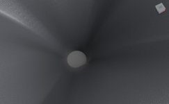
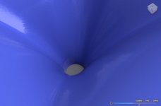
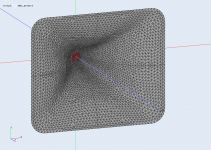
Renders of the deepest one -
Renders of the deepest one -
Attachments
Last edited:
Thanks for posting the sims.
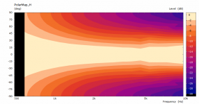
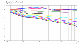
Your shallow wg looks exceptionally smooth, even far off-axis.
I suppose the irregularities in the latest sims may be artefacts that not really matter?
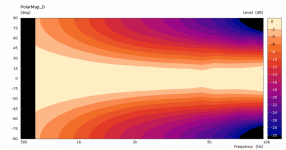
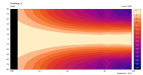
The latest p-map looks exceptional too.
The million-dollar question is: "How does the increased depth work out in real life?"
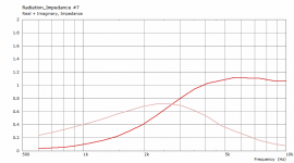
I expect a slightly better driver 'behaviour' towards the crossover frequency due to the higher radiation impedance.
Iow there's an improved coupling of the diaphragm to the air.
Your shallow wg looks exceptionally smooth, even far off-axis.
I suppose the irregularities in the latest sims may be artefacts that not really matter?
The latest p-map looks exceptional too.
The million-dollar question is: "How does the increased depth work out in real life?"
I expect a slightly better driver 'behaviour' towards the crossover frequency due to the higher radiation impedance.
Iow there's an improved coupling of the diaphragm to the air.
Last edited:
Yeah, that is still due to the coarse mesh, I didn't want to wait too long. Sometimes it's cleaner, sometimes there are defects like these on various frequencies. I'm already used to "look through" them...I suppose the irregularities in the latest sims may be artefacts that not really matter?
What does it mean for the driver?Iow there's an improved coupling of the diaphragm to the air.
Attachments
Two more... still experimenting with Fusion. 🙂
Attachments
Last edited:
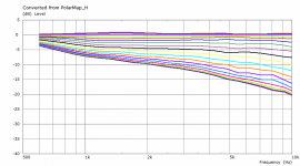
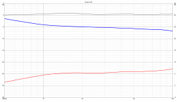
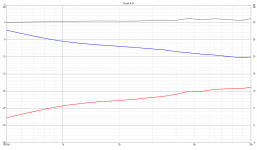
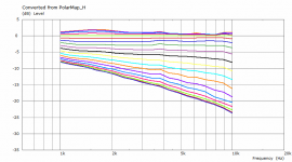
I loaded the horizontal polars into VituixCAD (great piece of work, BTW) for the wide and narrow waveguides shown above. There are DI calculated (correctly, I assume - the red curves). So these would be the DI curves if the waveguides were axisymmetric with these polars. If all the data was taken into accout it would be slightly worse I guess, maybe not that much. By far worst are the diagonals but they should not have a big effect on power response in this case.
Attachments

Last edited:
The shallow one (the first shown on the previous page) will be the one I will use now, together with a 12" midrange. As you can see, the DI of the waveguide itself is very gradual even under 1 kHz and that brings some freedom in crossover point and design.
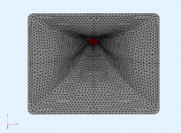
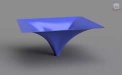
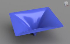
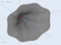
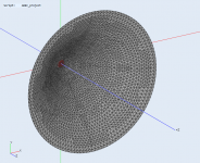
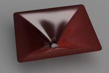
BTW, this is the basic shape before morphing to rectangle (200 mm deep in this case) -
BTW, this is the basic shape before morphing to rectangle (200 mm deep in this case) -
Attachments
Last edited:
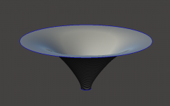
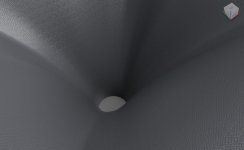
For the deepest one (220 mm) I tried to increase the corner radius to 50 mm. Not bad but not too visually appealing either 🙂
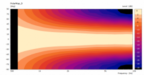
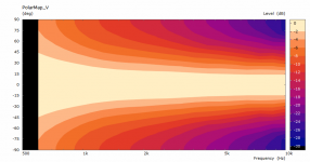
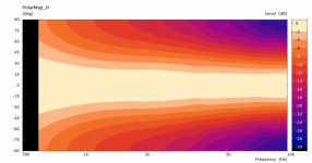
Maps normalized to 0 deg - no problem here.
Maps normalized to 0 deg - no problem here.
Attachments
For deeper waveguides it's probably hard to beat a "more OSWG like" variants - if it's big and smooth:
"More OSWG like" as in: Axisymmetric?
Btw, so far there's no definitive answer to your question "What does it mean for the driver?" I believe it (also) depends on the construction of the driver: compression ratio, design of the phase plug, exit section (or not) etc.
I meant, when you asked whether it isn't too shallow for 700 Hz, had you something specific in mind? Because I don't know why it should matter. Maybe you know.
The driver used should be capable of that I think.
The driver used should be capable of that I think.
Yes, the radiation resistance as a function of axial length, but I'm not convinced this applies to conical (type of) horns below 800 Hz.
But even if this were the case, you'll have to take the driver's specifics into account.
But even if this were the case, you'll have to take the driver's specifics into account.
Last edited:
mabat, your visualisations are things of beauty, thank you for posting. Very revealing of older commercially available designs.
A request if I may, please would you publish a legend for your charts? The DI charts from VituixCAD for example would be enhanced with this information for anyone not familiar with the colour coding in these.
Keep up the amazing and very generous work you are doing!
Cheers.
A request if I may, please would you publish a legend for your charts? The DI charts from VituixCAD for example would be enhanced with this information for anyone not familiar with the colour coding in these.
Keep up the amazing and very generous work you are doing!
Cheers.
And do you know how to do it?But even if this were the case, you'll have to take the driver's specifics into account.
As I understand the problem, it boils down to excursion and power handling, right? When you put a direct radiating dome tweeter in a flat baffle (i.e. the length of the horn is zero), how do you determine how low it can be used?
My "math" here is very simple - if an 18" OS waveguide, as shown below, can be used with a 1.75" diaphragm driver from about 900 Hz (and we know it can), then I have little doubts that a 3" diaphragm driver will handle 700 Hz in the waveguide shown above.
Attachments

And do you know how to do it?
As I understand the problem, it boils down to excursion and power handling, right? When you put a direct radiating dome tweeter in a flat baffle (i.e. the length of the horn is zero), how do you determine how low it can be used?
In principle, yes, except a compression driver has a front and back chamber, as well as a phase plug.
The latter, acoustically, is part of the horn path.
My "math" here is very simple - if an 18" OS waveguide, as shown below, can be used with a 1.75" diaphragm driver from about 900 Hz (and we know it can), then I have little doubts that a 3" diaphragm driver will handle 700 Hz in the waveguide shown above.
I'm sure it will, the mouth size is probably more important in this respect.
Morse defined a relationship between axial length and mouth perimeter.
I wonder whether the ATH4 actually qualifies as a conical horn, as the round-over takes up a significant part of the waveguide.
It's probably more a hybrid of sorts, like the K402.
Last edited:
- Home
- Loudspeakers
- Multi-Way
- Acoustic Horn Design – The Easy Way (Ath4)