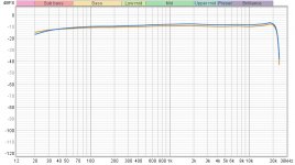
DI box "tube" circuit(With the tube effect turned all the way down) vs bypass. Both FR's are almost identical. The big difference is that the distortion is profoundly lower in bypass mode, and noise is about 6 db to 8db lower in bypass mode, So bypass mode with (massive) copper shielding wins.
I think it's very safe to say that the copper shielded DI box in bypass mode with the vibration sensor will give extremely accurate readings of side panel resonances, for under $50. It will also give accurate panel measurements in "Tube" mode(With the effect turned all the way down), if you don't mind the added distortion and noise.
I think it's very safe to say that the copper shielded DI box in bypass mode with the vibration sensor will give extremely accurate readings of side panel resonances, for under $50. It will also give accurate panel measurements in "Tube" mode(With the effect turned all the way down), if you don't mind the added distortion and noise.
Attachments

Last edited:
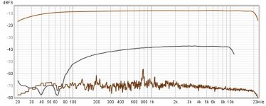
To add to the above measurements, the distortion on the second graph may simply be an artifact of the measurement conditions. I'll need to test it on an actual loudspeaker panel in both modes to make sure.
Both ways are identical..
1. KEF Q100 panel with bypass mode
2. KEF Q100 panel with "Tube modeling" circuit applied, but turned all the way down.
One thing is for certain, Q100 panels are terrible! 🙂
1. KEF Q100 panel with bypass mode
2. KEF Q100 panel with "Tube modeling" circuit applied, but turned all the way down.
One thing is for certain, Q100 panels are terrible! 🙂
Attachments
Last edited:
If anyone does decide to buy the Behringer AD121, I highly recommend the 9v wall wart. This thing has no on off switch, and if you forget to unplug the TS input, the battery will be dead the next time you go to use it.
Good work! Your AD121 is looking a little more 2000BC - meaning it has taken on the look of an ancient Egyptian artifact. 😀
Thanks for the new measurements and the comparisons of the two different modes. Your measurement rig really is taking shape.
Thanks for the new measurements and the comparisons of the two different modes. Your measurement rig really is taking shape.
Haha! The Golden Scarab!
It was worth doing the experiment, but if put in tube simulation mode with the blend dial turned all the way down, it's not needed for some reason. Oh well🙂
Shielding the input cable was absolutely beneficial in a huge way though.
It was worth doing the experiment, but if put in tube simulation mode with the blend dial turned all the way down, it's not needed for some reason. Oh well🙂
Shielding the input cable was absolutely beneficial in a huge way though.
Last edited:
What would happen if you took a (Dayton...) panel exciter, used it to record a panel's vibrations from the regular speakers when driven and nulled, then played back the recording with the regular speakers off - and at the same SPL as measured during the nulled method.
Would this give you a sense of how loud the panel vibrations actually are?
Would this give you a sense of how loud the panel vibrations actually are?
Play it back how? Do you mean with the exciter on the box? Clever, but I wonder if you could get levels to match? And would you need an exciter per box side to get the SPL?
Joe Jasniewski - I think I understand what you are getting at: attach the panel exciter to a panel on the speaker. connect the panel exciter to a mic preamp / audio interface and use it as a microphone... then play the speaker as you normally would and record the signal from the exciter. Repeat the process with the speakers nulled. Then play the signal back through the exciter and see how audible the panel vibration signal is. Is this what you are thinking?
That would be an interesting experiment, but it would miss the gist of what we're trying to do, which is to measure the interaction between the cabinet and the only "panel exciter" that really matters in this case, which is the midbass driver itself.
In reference to post #523..
It's an absolutely wonderful coaxial driver(Zaph) placed inside the cheapest cabinet they could build to bring the cost down to a target price point. 1/2" mdf with no bracing. I bought them because they were on sale for $250 a pair and just wanted the drivers🙂
Not only was it a bad cabinet, but driver and port placement on that cabinet caused big problems too, which were corrected for in future iterations.
Last edited:
What would happen if you took a (Dayton...) panel exciter, used it to record a panel's vibrations from the regular speakers when driven and nulled, then played back the recording with the regular speakers off - and at the same SPL as measured during the nulled method.
Would this give you a sense of how loud the panel vibrations actually are
Maybe I'm missing something. Please excuse my previous comment if I am.
My reply was spurred by someone mentioning physically connecting a regular speaker to the side panel; I dug through the last few pages, but cant find it to quote...
I bought three of these things, stuck them to the back of a solid body guitar - with all three connected to a polycarbonate plate, cut roughly in the guitar body shape, for something more for them to push against. They stick on using some 3M adhesive; 1st disadvantage of this idea is they're meant for "one time only" adhesion.
These things look like a basketless speaker with a plate attached to the VC, allowing attachment to a flat surface. The VC then pushes on that surface against the weight of its own magnet structure. One of these "turn any surface into a speaker" type devices that have been around since the 60's...
Of course, it'd work as a microphone. So the idea is record the panel vibrations using this thing using noise or music input to the speaker, then play that back through the same device still stuck to the same spot.
Crank up the amplitude of the playback level until the SPL is about the same as was measured under the nulled and blanketed condition.
Let's say you have two cabinets setup this way. Now you can put them back into the normal listening position to hear only what the cabinet wall vibration sounds like. You could inject cabinet wall noise due to pink nose (measured at some SPL level), and see if you can hear that (or not) when music is playing at that same SPL. Or is it completely masked?
Going really far out on this limb, you could make a filter that looks like the cabinet wall noise spectrum, run the music being played through that, flip the phase and perhaps cancel the cabinet wall noise by applying an opposing physical force using one of these devices.
Now there's a lifetime's worth of experimenting to get just right. Making active black hole cabinets...
Last edited:
Joe
I like the way you think!
I had a really fun time playing around with tactile "exciters" for a few years back in the early 2000's. Lot's of wacky experiments, but no aspirations of anything high end. I still occasionally have thought experiments involving those things🙂
I like the way you think!
I had a really fun time playing around with tactile "exciters" for a few years back in the early 2000's. Lot's of wacky experiments, but no aspirations of anything high end. I still occasionally have thought experiments involving those things🙂
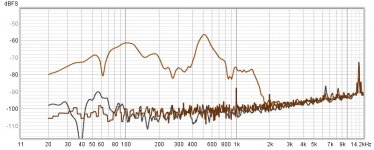
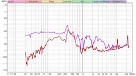
Piezo contact mic vs thin film piezo vibration sensor..
I imagine that the main difference in the response on the conventional contact mic is due to the picking up of sound through the air, which they are known to do.
Red trace - Thin film vibration sensor
All else is equal between measurements. All I did is switch one out for the other
I imagine that the main difference in the response on the conventional contact mic is due to the picking up of sound through the air, which they are known to do.
Red trace - Thin film vibration sensor
All else is equal between measurements. All I did is switch one out for the other
Attachments
Last edited:
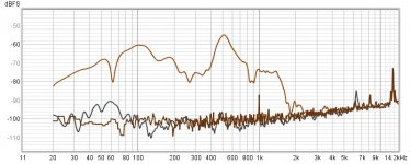
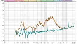
After doing the above measurement on an actively vibrating speaker side panel, the next measurement is with the contact mic vs the vibration sensor placed on the same spot on an inactive left channel speaker while the right channel speaker is playing a full range signal from 20hz to 20khz at 95dm/1m. This will give an idea of exactly how much sound is picked up(And not picked up) through the air with each.
Brown trace is the contact mic..
As you can see, the vibration sensor is picking up no sound at all from the opposite channel. The noise floor is all you can see.
On the contact mic, I think the reason its rolling off hard at 2khz is because it's at an extreme off axis angle to the tweeter on the right channel speaker.
Attachments
Last edited:
Yes. Even though they both work based on the piezo principle, one is clearly more suited for panel vibration measurements.
Last edited:
The idea I had about the Dayton transducers used to deaden panel vibrations is nicely captured here (start at about 10:00) Active Noise Cancellation - YouTube
He uses mics on the inside of the cabinet walls, because his design is for an unrecorded sound source. Since we know what the speaker is going to play, the internal mics could be dispensed with, IMHO.
He uses mics on the inside of the cabinet walls, because his design is for an unrecorded sound source. Since we know what the speaker is going to play, the internal mics could be dispensed with, IMHO.
- Home
- Loudspeakers
- Multi-Way
- Accelerometers to measure panel vibrations?