That looks like great progress.  Strange about the bypass mode, you'd think it would just bypass the effects. Good that you've found the proper settings now.
I am a bit surprised that you aren't seeing more box noise, only that bump around 600 Hz. If that's all there is, the boxes must be very dead. I'm not getting anything near that clean off of speakers here.
What software are you using for the measurements? In some softwares you can kind of null out the noise floor. Did you do new shielding? Mains noise is waaay down now.
Strange about the bypass mode, you'd think it would just bypass the effects. Good that you've found the proper settings now.I am a bit surprised that you aren't seeing more box noise, only that bump around 600 Hz. If that's all there is, the boxes must be very dead. I'm not getting anything near that clean off of speakers here.
What software are you using for the measurements? In some softwares you can kind of null out the noise floor. Did you do new shielding? Mains noise is waaay down now.

That looks like great progress.
I am a bit surprised that you aren't seeing more box noise, only that bump around 600 Hz. If that's all there is, the boxes must be very dead. I'm not getting anything near that clean off of speakers here.
What software are you using for the measurements? In some softwares you can kind of null out the noise floor. Did you do new shielding? Mains noise is waaay down now.
The bump I'm getting at around 600hz is while playing the speakers very loudly with a full sweep at around 95db/1m.
REW. There are a lot of settings I'm not totally aware of, but I'm constantly poking around and learning.
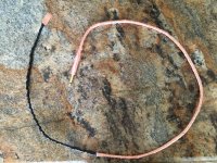
Yes, I also shielded with grounded copper tape and twisted cables, but it made surprisingly little difference until I changed the settings on the DI box. I tried the different settings on the DI box out of pure frustration. It went totally against my sensibilities. I was very surprised when I got these results.
I'm also very surprised at how different the resonances are with the sensor placed in the exact center of each side of the same box.
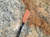
The copper goes from the plug, all the way to the sensor. Nothing was left to chance🙂
Attachments
Last edited:
REW, thanks. Your REW exports look different than what I'm used to, I didn't recognize them.
As for the DI, do you think that before in "bypass mode" it was giving you a bass boost that was elevating noise? Or maybe now there is a bass cut that is burying the 60 Hz?
As for the DI, do you think that before in "bypass mode" it was giving you a bass boost that was elevating noise? Or maybe now there is a bass cut that is burying the 60 Hz?
Pano
I could be wrong, but I think that the DI box was simply acting like an an excellent EMI antennae when in bypass mode.
With the "effects" dials turned all the way down, I'm assuming that those "effects" are being turned off, but I could also be wrong about that. I'll look at the manual again.
I could be wrong, but I think that the DI box was simply acting like an an excellent EMI antennae when in bypass mode.
With the "effects" dials turned all the way down, I'm assuming that those "effects" are being turned off, but I could also be wrong about that. I'll look at the manual again.
Last edited:
Pano
That's electrical tape over the copper on the twisted wires to hold it all together.
Okay, the bass, mid, and treble dials are only level controls for each, so if they're all set at the same level, the DI will have a linear output. The "blend" control on the other hand, is the vacuum tube modeling effect and will add more or less modeling based on the level set, so when you turn that dial all the way down, you are getting a linear, distortion free signal.
I also looked thru the manual. Yes, if the tone controls are straight up, there should be no EQ. That Blend control worries me tho. The manual says:
It's that "some of" that makes me suspicious. It seems to imply that it never goes totally dry. The bypass switch should just act as a wire with gain and impedance buffer. But you found that it wasn't.
The BLEND control activates the integrated tube/microphone emulation circuitry. In most cases, you will probably set it to maximum (100%). If you want to hear some of the distinct timbre of a piezo pickup or reduce the amount of compression, simply turn the control counterclockwise
It's that "some of" that makes me suspicious. It seems to imply that it never goes totally dry. The bypass switch should just act as a wire with gain and impedance buffer. But you found that it wasn't.
Good call, but I'm pretty sure that since this is a panel vibration measurement instead of an audio measurement, the need for a "Wire with gain" level of resolution isn't nearly as important as it would be otherwise.
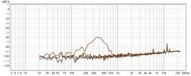
Here is the side panel resonance plus thd and noise with speaker playing a sweep at 100db/1m, with the tube modeling blender turned all the way down. If there was a lot of tube modeling "Processing" going on, I would imagine that thd and noise would be higher than what it is.
Here is the side panel resonance plus thd and noise with speaker playing a sweep at 100db/1m, with the tube modeling blender turned all the way down. If there was a lot of tube modeling "Processing" going on, I would imagine that thd and noise would be higher than what it is.
Attachments
Last edited:
Yep, hard to say. Do you happen to have the cable needed to do a loop measurement with the DI in the loop? Maybe RCA to 1/4". That's a way to know for sure what the Berhinger DI is doing, or not doing.
Pano
I just purchased a balanced to TRS cable. I'm interested in what the DI is doing on this setting also. It will come off of an open crossover output(No filter applied) and back into the DI box. Luckily, there is a -20db pad switch on the DI for higher signal levels.
I just purchased a balanced to TRS cable. I'm interested in what the DI is doing on this setting also. It will come off of an open crossover output(No filter applied) and back into the DI box. Luckily, there is a -20db pad switch on the DI for higher signal levels.
Last edited:
OK, you are not coming straight from a soundcard, nut from your crossover. The balanced to TRS might work. You'll want the level coming out of the crossover to be very low. I don't know what's the max level the DI can take on the piezo input.
I just switched it to a 1/8" to TRS cable. The DI should have no problem with the input signal now. There is no rca output off the computer, so this is the best I can do. The -20db pad switch on the DI should also help.
Last edited:
Just remember that the 20dB pad is on the output. Keep the level low coming into the DI, or you'll see a lot of distortion.
Oh jeez, your right! I'll have to keep my fingers crossed that it'll work with a low enough input signal. I decided to get both cables to see which situation works best.
It will be pretty cool if the di turns out to be neutral in this mode with the adjustments. The other way was not working well at all with the high emi.
It will be pretty cool if the di turns out to be neutral in this mode with the adjustments. The other way was not working well at all with the high emi.
Last edited:
Turn down all the analog controls that you can. Then turn the REW signal levels way down. You might need to be at -30dB or lower.
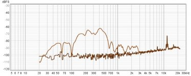
I really want to use bypass on the DI box for obvious reasons, so I went for an all out shielding effort. Each thing I did dropped the Emi a little bit further, to the point that it’s perfectly useful in that mode. It was fun to see the results after each stage. The first stage was the input cable, the second was the box and the third was the output cable which was creating another loop. The 60hz hum is now down to negligible levels in the bypass mode.🙂
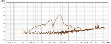
As you can see, the panel resonances are now very easy to differentiate from the noise floor. This was with a 95db/1m output on the mid, with no crossover filters applied
Second graph is the opposite panel, same cabinet.
As you can see, the panel resonances are now very easy to differentiate from the noise floor. This was with a 95db/1m output on the mid, with no crossover filters applied
Second graph is the opposite panel, same cabinet.
Attachments
Last edited:
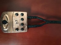
In reference to the above, essentially anything made of plastic that was not already shielded was wrapped with copper shielding tape.
A metal di box would be better(maybe) than the plastic Behringer, but the only one I could find that compared spec wise is $230 compared to the $30 Behringer. Shielding it with copper tape was a small price to pay.
A metal di box would be better(maybe) than the plastic Behringer, but the only one I could find that compared spec wise is $230 compared to the $30 Behringer. Shielding it with copper tape was a small price to pay.
Last edited:
I have a feeling I know why the side panel resonances are different on both panels. The CLD baffle I made has a very narrow fit in the recess on the cabinet and the metal parts may be contacting parts of the baffle in certain places, which would bypass any benefits of the CLD and could explain for the differences between the two sides. My next step is to widen the recess another 1/8" all the way around to provide for more clearance.
- Home
- Loudspeakers
- Multi-Way
- Accelerometers to measure panel vibrations?