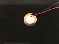
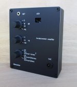
What do your peizo disc mics look like?
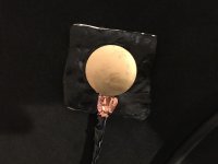
The raw piezo disc was picking up so much sound that I decided to use a patch of Noico car panel deadener on top, which also acts as a really good reusable adhesive. As you can imagine, it helped a lot, but surprisingly it still picks up a ton of airborne sound
Attachments
Last edited:
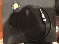
Just found this. If you really want to do the thin film piezo measurements with a laboratory grade device, it will cost you $400, which is actually less than I thought it would be. I think I'll stick with the Behringer. I have to admit, it is pretty tempting though. It comes with everything you would need, including the bnc cable with the piezo sensor already connected🙂
https://www.te.com/commerce/Documen...S_Piezo_Film_Lab_Amplifier_A1.pdfCAT-PFS0015
https://www.te.com/commerce/Documen...S_Piezo_Film_Lab_Amplifier_A1.pdfCAT-PFS0015
Last edited:
Thanks Remlab. I'm surprised that with that big square of Noico it could pick up anything at all. Did you test it free air, or attached to something?
Attached, with the Noico on top of it. My goal was to see if I could make it somewhat similar to the thin film piezo type, which would have been cool, but it obviously didn't work🙁
@Joe J. I feel that the exciter as vibration test is clever, but I suspect it will be tricky to use. Perhaps a procedure like this could work.
- Use a piezo strip a la Remlab to measure panel vibration caused by the woofer.
- Attach an exciter to the panel and run a sweep thru it measured by the piezo.
- Compare signal the exciter measurement to the woofer measurement and make a correction file.
- Use that correction to playback thru the exciter and listen to the box.
- Double check with the peizo that the exciter is doing the same that the woofer did to the panel.
If the objective is to fix a perceived problem with the box and the exciter turns a box into a "speaker", you could place the exciter on a box wall, then run an REW sweep through it and measure the acoustic result.
Maybe pick a peak, set an oscillator to that frequency, verify the enclosure ring by ear. Then empirically try to cancel it by moving a brace or post about the inside of the box - like they tune a violin's sound by moving the "sound peg" around. Or apply whatever method until you can dampen that one. Rinse and repeat until that wall is "done".
I imagine you could spend all day at this, trying different cabinet walls and positions of the exciter, positions of a brace or post. Maybe it makes it worse by just squeezing the energy over to a different frequency that's actually louder! It would be interesting to see if a brace or post can knock out more than one resonance frequency, or if a post or brace could be designed as a meta material that would do that. Imagining a wood post with a piece of sorbothane between two segments, or some such arrangement.
Of course, inserting too many objects inside the cabinet is going to muck with the volume a bit, so you could end up with a nicely non resonant cabinet that doesnt work with the speakers anymore...
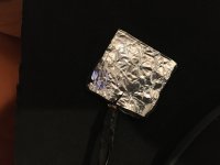
I'm still having trouble imagining how to get around the one-time stick-on interface these exciters come with. You could stick it once to something, then stick and peel that to the cabinet wall multiple times; but what would that something be? Dunno... A disc of Aluminum?
Maybe pick a peak, set an oscillator to that frequency, verify the enclosure ring by ear. Then empirically try to cancel it by moving a brace or post about the inside of the box - like they tune a violin's sound by moving the "sound peg" around. Or apply whatever method until you can dampen that one. Rinse and repeat until that wall is "done".
I imagine you could spend all day at this, trying different cabinet walls and positions of the exciter, positions of a brace or post. Maybe it makes it worse by just squeezing the energy over to a different frequency that's actually louder! It would be interesting to see if a brace or post can knock out more than one resonance frequency, or if a post or brace could be designed as a meta material that would do that. Imagining a wood post with a piece of sorbothane between two segments, or some such arrangement.
Of course, inserting too many objects inside the cabinet is going to muck with the volume a bit, so you could end up with a nicely non resonant cabinet that doesnt work with the speakers anymore...
I'm still having trouble imagining how to get around the one-time stick-on interface these exciters come with. You could stick it once to something, then stick and peel that to the cabinet wall multiple times; but what would that something be? Dunno... A disc of Aluminum?
A nice option I have with my system, is that I can set the crossover for each module so that each primary module resonance can be filtered out with surgical precision while still respecting the limitations of the drivers. It's extremely effective. I have them set at 65hz, 250hz, 500hz, and 2khz, with 8th order slopes. I will be showing before and after graphs in a few days. In the mean time, I'm still having some EMI problems with the piezo input cable that I'd like to completely iron out. The simple movement of the sensor from one cabinet to another, changes the EMI for better or worse. I'd like it to be consistent from one graph to the next.
Last edited:
IF the exciter is also an effective microphone for vibration pickup, its low impedance VC would be hard to beat EMI wise. Particularly if you ran it differential; two wires within a grounded shield, electrically grounded to the exciter frame, into an standard XLR mic input.
Of course, I havent actually done that, just speculating.
Of course, I havent actually done that, just speculating.
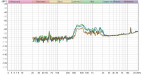
Have some more interesting data involving the loudspeaker stand interface. I need to get some blu tack type product also for testing. So far, Sorbothane wins... By a lot. But the competition so far, sucks🙂
Green-Spikes
Blue- nothing
Brown-Sorbothane
I also tried a neoprene sheet, but believe it or not, it was identical to the spikes.
Green-Spikes
Blue- nothing
Brown-Sorbothane
I also tried a neoprene sheet, but believe it or not, it was identical to the spikes.
Attachments
Last edited:
Yes, the items are placed between the stand and the speaker, and the sensor is placed on the center of the side panel. I did make a mistake though. This is with the crossover set at 500hz and 2kz. I'll do more measurements with only the 2khz applied next time(The Sorbothane might not do as well in that situation. John Atkinson did the same type of testing back in '94. I thought it would be interesting to reprise it and add a few things, like Noico car panel deadener to the test and of course, Sorbothane.

Yes. Actually, it was '92 when Atkinson did this study with the accompanying article. It has a ton of really good info for anyone who's interested.
The Sound of Surprise (the loudspeaker/stand interface) | Stereophile.com
The three Sorbothane feet used in his study were very thick(not good) and only three were used(Also not good). It needs to be a relatively thin sheet and all four corners of the speaker need to be supported with it. In other words, it needs to used in the same way he used the Blu-tak.
Last edited:
I bought some Blu-tak style putty to do a direct comparison with the correctly used sorbothane. The Noico product used the same way should also be an interesting comparison.
Last edited:
Thanks for the article links. The Blu-Tak did very well. Waiting to see what you find with other materials.
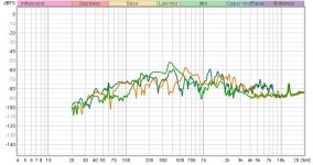
1. The side panel resonance of all three modules with no crossovers applied..
2. The side panel resonances with crossovers applied to specifically deal with the primary resonances of each..
It should also be noted that what is left is extraordinary low in level compared with the module outputs of 90db/1m
3. The subwoofer panel resonance will be a tougher nut to crack🙂
2. The side panel resonances with crossovers applied to specifically deal with the primary resonances of each..
It should also be noted that what is left is extraordinary low in level compared with the module outputs of 90db/1m
3. The subwoofer panel resonance will be a tougher nut to crack🙂
Attachments


Last edited:

- Home
- Loudspeakers
- Multi-Way
- Accelerometers to measure panel vibrations?