Making some progress now that I have nearly all the parts. I had to order the adapter separately to use with the Mean Well 36V PSU from the store so that will be the critical path item before I can bias and get tunes playing. It's only a couple bucks on Mouser, but man it sure would be nice if the store kit included the adapter (PLUG-R7BF-PM1).
I used 47ohm gate resistors based on @PSz. post #24. I'm not sure what is the ideal value here for gate resistor, but felt if the lower 47ohm that PSz. used works vs the 100ohm on the schematic, I'd give that a try. Other than that I'm populating based on the components in the BOM/schematic.
Should be ready to power up as soon as the Mouser order arrives with the plug adapter late next week.
Thank you to everyone who made this build a reality! What a great kit to have in the store in the not too distant future. A fun and relatively straight forward build so far!
Last edited:

Making this the project for an Amp Camp event is certainly possible, but a bit more involved than what I've done prior because I would need to get the appropriate number of chassis to California (the diyAudio warehouse is in Massachusetts). Something to consider...
Thanks to Nelson for the PCB's, they are quality boards. I plan to drill and tap heatsinks and complete chassis this weekend.
Would the 2022 Front End be of use with this amp?
Here are some photos of progress so far:


Would the 2022 Front End be of use with this amp?
Here are some photos of progress so far:
Anand, thank you for the reply.
I expect 14dB will be enough gain. I have an old Threshold NS10 preamp that has more gain than average, and plan to build Wayne's 2018 preamp too. My system(s) is a mixed bag of home theater system (with DIY Zaph MTM/Dayton RSS315 sub) with class D driving it. But I am building a front room system so I wont bother the wife and kids. For now that will be an MLTL 6" designed by Neil Blanchard. I may try the 2022 FE out with this just to see how it works and of course good with a MoFo and other stuff to come.
Regards,
Roger
Well, I was so excited to finally have everything wired up, but alas, I'm getting the dreded SMPS pulsing that's telling me I probably broke something. I did have the switch originally connected wrong, but I don't think that should have fried anything. All pots were full CCW.
Scratching my head staring at a schematic right now. I'll reread the thread and see if I can get some measurements using my bench power supply and limiting current. I should have started there, but didn’t have a barrel connector that fit. Should have just bought one and waited for it to arrive.....future builders, learn from my impatience.

Scratching my head staring at a schematic right now. I'll reread the thread and see if I can get some measurements using my bench power supply and limiting current. I should have started there, but didn’t have a barrel connector that fit. Should have just bought one and waited for it to arrive.....future builders, learn from my impatience.
Perhaps the washers over the mosfets are too large and are touching and shorting out the circuit?
It's a good question to ask, but I paid close attention there, used extra tall standoffs and was sure to cut the wires extending through the board very short.
Very good point for anyone building this to be extra sure you don't short any wires if using a washer.
My only thought is my misswired switch may have fried something. I double and triple checked my connections, but somehow got "COM" mixed up with the thought that meant ground, so I was triple checking the wrong assumption. So its possible I applied -36Vdc in where I should have been +36Vdc.
{Insert head being banged into wall here.}
Last edited:
Take a look at the picture of the assembled boards in post #15. It looks like your trimmers are mounted in the wrong orientation. So the fix is to adjust the trimmers to full clockwise before powering up.
Ok, I'll check again. I paid extra special attention there as well based on the thread comments. I took Mark Johnson and ItsAllInMyHead comments to heart as I used in line trimmers. My understanding is the new boards are set up so full counterclockwise is start up position. I used a single turn pot with the triangle pints to figure out what orientationI needed. Still going to put some effort in and check again. I probably did it wrong even though I spent a lot of time and effort to get it right. Thanks!
[EDIT: On the plus side, I'm the perfect "tester" to find all the dumb ways to screw up so we can warn others in advance..."Don't do what birdbox did" 😉 ]
[EDIT: On the plus side, I'm the perfect "tester" to find all the dumb ways to screw up so we can warn others in advance..."Don't do what birdbox did" 😉 ]
Last edited:
Ok, I didn't know that the boards were changed. Perhaps Nelson could include information in post #1 to help builders easily find all information that would help diyers with their build.
Edit: I read Nelson's post re:CCW setting. He switched the pcb traces. The orientation of the trimmer should therefore remain as shown previously. So you should go CW with your trimmer orientation.
Edit: I read Nelson's post re:CCW setting. He switched the pcb traces. The orientation of the trimmer should therefore remain as shown previously. So you should go CW with your trimmer orientation.
Last edited:
Ok, I'm gonna give that a try. I've been trying to measure the pots while soldered in but not working out. I'm not sure how I can pay so close attention to something and still royally screw it up. Can't fix dodo I guess.
BTW, Thank you @Ben Mah !!
[EDIT: So with all pots full clockwise I measure basically 0 ohms across all pin combinations (1-2, 1-3, 2-3). Before I apply power, I'm hoping someone can confirm starting at near zero resistance is correct. I'm not smart enough on the how the circuit works to feel confident that's correct. My mind tells me "start with high resistance" to keep current down. Clearly that's just my lack of understanding of how the pots control the bias/offset. I'm gonna stare at the schematic a while and see if I can apply some smarts (still have a tiny bit of those left) to figure this out.]
Last edited:
Starting at zero ohms is what you want 😉
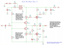
A bit of explanation in the attached image. Hopefully that helps build some understanding. I've always found it easier to avoid mistakes when I have some intuition about how things are working. And I often learn the most shortly after making a mistake
A bit of explanation in the attached image. Hopefully that helps build some understanding. I've always found it easier to avoid mistakes when I have some intuition about how things are working. And I often learn the most shortly after making a mistake
Attachments
Thank you @N Brock !
That helped put the final piece in the puzzle for me. I had to go quick watch these animations just to build a visual of what you wrote.
N-Channel MOSFET Animation:
P-Channel MOSFET Animation:
Here's where I was when you sent out the "full assist" post...
Not doing bad as I had the 3296 schematic out and studying that, but was still a little off on the key to understanding how the pot resistance affected the bias current through MOSFETs. Sharing my chickenscratch for "funsies".

Now, on to power up with significantly more confidence and a little better understanding. Thank you again!
[Edit: Houston, we have liftoff of the ACP MiniMax on its way to playing some glorious music!]

That helped put the final piece in the puzzle for me. I had to go quick watch these animations just to build a visual of what you wrote.
N-Channel MOSFET Animation:
P-Channel MOSFET Animation:
Here's where I was when you sent out the "full assist" post...
Not doing bad as I had the 3296 schematic out and studying that, but was still a little off on the key to understanding how the pot resistance affected the bias current through MOSFETs. Sharing my chickenscratch for "funsies".
Now, on to power up with significantly more confidence and a little better understanding. Thank you again!
[Edit: Houston, we have liftoff of the ACP MiniMax on its way to playing some glorious music!]
Last edited:
Thank you again to @Ben Mah and @N Brock for your help!!!
Finally got the chassis back together and a good starting point to really dial in the bias. I'm going to likely target 0.8A, but I'll let the heat sinks make the final call.
What offset voltage is a good target? 17.1-17.4Vdc would match the same ratios as Nelson's article on ACA Mini, so that was going to be my guide unless someone has another suggested target/range.
All dialed in for bias and the 17.4V Vo, but when I turn on the amp, the DC offset on the speaker terminals starts out around 3V. It slowly drops over a few minutes uses down to 10mV. Should I be concerned about a 3V offset on power up?
I'm not gonna worry about DC offset. It's basically at 0V now and the music sounds so fantastic, nothing else really matters.
Bias is 0.82A on both channels and Vo of 17.4V on both channels.
Thank you Papa and Nelson Brock!
This is one outstanding sounding amp. It's going to bring a lot of people into DIYaudio world after it hits the store.
"Superb!"
... is what I'm gonna say when folks ask 'how does it sound?'
Bias is 0.82A on both channels and Vo of 17.4V on both channels.
Thank you Papa and Nelson Brock!
This is one outstanding sounding amp. It's going to bring a lot of people into DIYaudio world after it hits the store.
"Superb!"
... is what I'm gonna say when folks ask 'how does it sound?'
Last edited:
@birdbox
6L6 is right. Next time the amp is back at the bench, connect a throwaway test woofer/speaker (i.e. a load) to the speaker outputs and measure the dc offset on turn on again. I’ll be curious to see if the offset is as high and how long it takes to settle. That’s a more ’real world’ test.
Enjoy the music, you are in for a treat!
Best,
Anand.
- Home
- Amplifiers
- Pass Labs
- ACA MinMax - ACA mini retrofit for ACA chassis