Great new!!!! I hope that @PSz posts his experience and photos here. Looking forward to this being declared "good to go."
Hold the phone, @PSz. found an issue with the board and schematic!
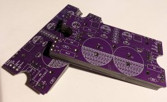
On my boards P1 is connected to the switched side of the V+ rail when it should be connected at all times. I missed this when transcribing the original schematic into KICAD I'll have it corrected for the next go-around.
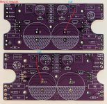
To fix the Rev 0 boards, cut the trace connected to the right most terminal of P1 and add a wire from there to the positive terminal of C3 on the rear side of the PCB. (I added front and back views for clarity, but only one wire per board is needed)
On my boards P1 is connected to the switched side of the V+ rail when it should be connected at all times. I missed this when transcribing the original schematic into KICAD
I'll have it corrected for the next go-around.To fix the Rev 0 boards, cut the trace connected to the right most terminal of P1 and add a wire from there to the positive terminal of C3 on the rear side of the PCB. (I added front and back views for clarity, but only one wire per board is needed)
Attachments

Last edited:

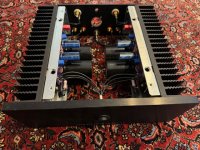
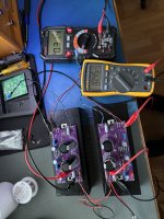
Two channels are biased up and behaving well on the kintsugi Rev 0 boards currently at 36V and 0.8A.
This pair is running IRFP140 and IRFP9140 outputs where:
P1, P2 are multi turn 1K
R2, R3 are 221K
R4 is 6.8K
R8, R9 are 0.47R
R10 is 0.33
R12, R13 are 47R
R11 and C6 are omitted
Power supply is the Meanwell GST160A36-R7B with the DC PLUG-R7BF-P1M adapter.
This pair is running IRFP140 and IRFP9140 outputs where:
P1, P2 are multi turn 1K
R2, R3 are 221K
R4 is 6.8K
R8, R9 are 0.47R
R10 is 0.33
R12, R13 are 47R
R11 and C6 are omitted
Power supply is the Meanwell GST160A36-R7B with the DC PLUG-R7BF-P1M adapter.
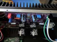
These boards are excellent to work with and very well laid out. Test points and trim pots are easily accessible with the lid open. All the chassis wiring is clean, short and intuitive with the mirror imaged boards. Great job N Brock!
With my output devices and associated parts the bias is now set a bit over 1A with the 36V supply. Bias does drift upwards as the amplifier comes up to temperature so set it a bit low then adjust it as it stabilizes.
With my output devices and associated parts the bias is now set a bit over 1A with the 36V supply. Bias does drift upwards as the amplifier comes up to temperature so set it a bit low then adjust it as it stabilizes.
Attachments
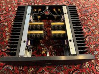
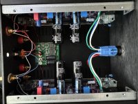
Got both boards both up and running today. Bias and voltage are rock solid.
Only change was the one noted, cutting at P1 and adding a wire to + C3.
Next step put the case together and put some music through it.
Thanks Nelson Pass for this great sounding little class A amp. And many thanks to N Brock for creating this board that fits the ACA case perfectly.
Only change was the one noted, cutting at P1 and adding a wire to + C3.
Next step put the case together and put some music through it.
Thanks Nelson Pass for this great sounding little class A amp. And many thanks to N Brock for creating this board that fits the ACA case perfectly.
Attachments
Even with the stock circuit you should bump up the bias with these heatsinks. Doubling it should not be a problem.
Do you have insulators between your output transistors and the mounting screws? If not then you should add them.
The switch is a Latching push button DPDT with 24 v LED illumination. 19mm mounting hole.
https://www.amazon.com/dp/B07GNN1S93?psc=1&ref=ppx_yo2ov_dt_b_product_details
Works good with the mirrored boards. Make sure to sort out the wiring diagram before you connect.
https://www.amazon.com/dp/B07GNN1S93?psc=1&ref=ppx_yo2ov_dt_b_product_details
Works good with the mirrored boards. Make sure to sort out the wiring diagram before you connect.
Thanks: the socket was what especially interested me. How difficult was it to terminate wires into the socket, or did you just use the pigtails that appear to be included with the socket?
The switch itself is separate and there’s a plug with pigtails attached that plugs into it. The one caveat about this plug, there is no top or bottom notch, as other plugs have, so you can plug it in upside down, which creates a problem and shuts down the power supply (experience talking 🙄) and can cause some increased heart palpitations.
I've just updated the first post with the corrected schematic and Rev 1 board layout. I'll be ordering a small batch of the new boards later today to build and validate them
Rev 1 changes:
Fixed issue described in post #22
Updated pin spacing of super cap to 3mm (was 5mm)
Increased spacing and pad size of test points
Added NC / COM / NO text to switch pads
Larger text in a few areas
Rev 1 changes:
Fixed issue described in post #22
Updated pin spacing of super cap to 3mm (was 5mm)
Increased spacing and pad size of test points
Added NC / COM / NO text to switch pads
Larger text in a few areas
Yipee!!!! Thank you for your efforts, as well as those that contributed information that lead to the revisions.
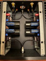
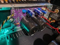
Build and test of the Rev 1 boards went well! Like Paul I used IRFP140 / IRFP9140 with 0.47Ω degenerating resistors. I tried to bias with a single turn pot and it was too sensitive, much easier to adjust once I swapped to multiturn pots. I've changed the BOM to make these the "standard" parts.
Bias is stable at 1.1A and heatsinks are 30°C above ambient temp. Listening to it now and wow, it does a fantastic job on the lower efficiency (and I suspect complex impedance) bookshelf speakers I use at my desk that the ACA struggled with a bit. Later tonight I'll have a listen on the SLOBs.
For those who don't like to wait, I've got a small set of extra Rev 1 boards available, let's say $10 per pair plus actual shipping cost. When I do a larger quantity order, I'll go for the extra bling ENIG (gold) finish.
Attachments

- Home
- Amplifiers
- Pass Labs
- ACA MinMax - ACA mini retrofit for ACA chassis