Mechanisms may be different as you say, but end result is the same: 2H of filament AC at the amplifier output, which will intermodulate with other frequencies. 2H of AC line coming from imperfectly filtered supply, or picked up as hum at the input will have exactly same effect.It's not about the heating effect...
With the hum-pot connected to ground (or an Rk + Ck cathode bias network), the two ends of the filament ride up and down with the line frequency, in antiphase. That means the anode-cathode voltage is modulating at the two ends.
The potential may average out on a thermal timescale, but the instantaneous emissive anode current depends on the instantaneous voltages, at each point.
And because the curves are not symmetrical (above and below the idle operating point) the differences in current do not fully cancel. This does not happen with a grid signal, and DC heating - it's a distortion mechanism unique to AC heating.
The grid-to-cathode voltage is also modulated by AC-heating, but that does happen with a music signal at the grid - naturally.
You are assuming that the effect of one and the same voltage simultaneously modulating grid-to-cathode and grid-to anode voltages is equal to simply modulating the grid voltage.Mechanisms may be different as you say, but end result is the same:
I think that's highly doubtful - and would certainly require measurement to pass scrutiny.
sser2,
You do not see the difference.?
1. An amplifier with only music at the RCA input connectors, and no hum or other signals anywhere in the amplifier. The only intermodulation is the music tones with them each other.
2. The music Plus non-musical signal (power mains related) that all are subject to the amplifier's Inter-modulation distortion.
Sure it depends on construction and other things for its extent, but we already have examples of measurement on seemingly benign example: including the contribution from Euro21 right on this thread - a 300B PP at 1W.That's why I Said it depends on tube construction. The effect may be below the noise floor, in other words, not audible. Or it may be audible
Given the relatively low Vf of 5V of the 300B, and the cancellation potential of the push-pull connexion, we might expect a low IMD value for this case. But instead we find spurs in the output of ~45dB down. That's certainly not something that can be ignored:
Euro21's IMD spectrum for 300B PP @1W
sser2 (answers A) and anatech (answer B),
A. You do not see the difference.?
1. A really good DHT amplifier with DC on the filaments: There is Zero hum at the loudspeakers. Good.
Then, with only music at the RCA input connectors, the only intermodulation is the music tones with each other.
Good.
2. A really good DHT amplifier with AC on the filaments: There is Zero hum at the loudspeakers, because the hum balance pot is adjusted. So far so good.
Then, with only music at the RCA input connectors, the intermodulation is the music tones with each other,
AND (plus) the intermodulation of 2 x the power mains frequency with each and every music tone.
B. Take a 45, 2A3, 300B, 211, 845, 212E, etc. The architecture, and general form of the filament, grid, and plate are much more alike and similar, versus the differences between them.
The biggest difference of any two tubes of one type, and between each of these tube types to each other . . .
Is how tightly controlled the tolerances are of each individual tube, no matter the tube type.
Example of poor tolerance control: The "plane" of the W filament was not evenly spaced to one side of the grid "plane" versus the space to the other side of the grid "plane".
The result of poor tolerance control . . . is just like two tubes in parallel where the plate resistance, transconductance, and u are not matched between the parallel tubes.
The last issue of Glass Audio's cover article discussed the issues of un-balanced parallel tubes,
And the poor tolerance control of a DHT with un-even spacing. Three of us did the research, and we wrote the article.
There is so much that can impact what you hear. Masking by the music for one. Then the dynamic range available in your listening space which has a lot to do with noise floor, and the efficiency of the speaker system. It's too easy to look at measured results and condemn things out of hand, but in the actual application it may not really matter.
I have measured some truly horrible pieces of equipment, tube and solid state. Oddly the owners may consider them to sound excellent. Now, I know what they sound like and would never accept that performance, but that is in my space. Who knows what other factors are involved where they listen.
Spikes on the IM do sound pretty bad in my estimation, but I have seen worse than -45 dB (1 watt) and it may be heard as "the sound of tubes" by the observer. So from many decades of experience in the audio field, I am not so quick to judge under these conditions.
6A3, you are so right about manufacturer variability (QC)! Then when it comes to throwing two very dissimilar output tubes together in parallel - sheesh! That adds and entirely new dimension to everything, including hum cancellation and distortion. That is precisely why I only use modern production parts where quality control is acceptable. I also avoid running tubes in parallel. Using parts made by hand ... holy crap! They will never, ever be consistent like a well made current part. Never mind material consistency in the part. Using DHTs is cool, I get that. They have their sound that some people really like. That's cool. But we are talking about parts that were hand made with poor materials control compared to today. So if you like the sound and everything else, that's more than fine. But do accept imperfections because you have decided to use hand made components.
Yes, as I said, the definitive test would be to compare filament IMD with general IMD in the same amplifier, or, even better, in a number of different amplifiers. I bet these two IMDs will closely follow each other.You are assuming that the effect of one and the same voltage simultaneously modulating grid-to-cathode and grid-to anode voltages is equal to simply modulating the grid voltage.
I think that's highly doubtful - and would certainly require measurement to pass scrutiny.
I have no incentive to do such test. I am not making SE amplifiers. PP amplifiers are fine with AC filaments under conditions of low open loop distortion. Since you are invested in this, the burden of proof is yours.
We keep repeating the same arguments.sser2 (answers A) and anatech (answer B),
A. You do not see the difference.?
1. A really good DHT amplifier with DC on the filaments: There is Zero hum at the loudspeakers. Good.
Then, with only music at the RCA input connectors, the only intermodulation is the music tones with each other.
Good.
2. A really good DHT amplifier with AC on the filaments: There is Zero hum at the loudspeakers, because the hum balance pot is adjusted. So far so good.
Then, with only music at the RCA input connectors, the intermodulation is the music tones with each other,
AND (plus) the intermodulation of 2 x the power mains frequency with each and every music tone.
I can rephrase your point 2 like this:
A really good DHT amplifier with AC on the filaments. There is zero AC fundamental hum at the speaker due to adjustment of hum bucking pot, but 2H hum resulting from tube's non-linearity is not zero. It appears at the speaker and intermodulates each and every music tone, the same way that different music tones intermodulate each other.
On careful looking at this graph, the +/- 50 Hz side bands are the most prominent. The +/- 100 Hz bands are pretty benign at -70 dB. What does it prove?Sure it depends on construction and other things for its extent, but we already have examples of measurement on seemingly benign example: including the contribution from Euro21 right on this thread - a 300B PP at 1W.
Given the relatively low Vf of 5V of the 300B, and the cancellation potential of the push-pull connexion, we might expect a low IMD value for this case. But instead we find spurs in the output of ~45dB down. That's certainly not something that can be ignored:
Euro21's IMD spectrum for 300B PP @1W
That's the second post suggesting in a gentlemanly way that hearing an impact is related to 'improper' design and/or inadequate parts. As a data point my experience was using:There is so much that can impact what you hear.
- indirectly heated tube
- pentode SE output with global feedback
- THD 0.35% 2nd and about 0.03% 3rd at one watt, no other harmonics greater than -100 dB
- James OPT
- no visible IMD skirts visible on single tone with DC filaments
- 100% modern polypropylene caps (Kemet) at a minimum
- no carbon resistors
- copper wire (!)
No woo beyond the SE topology. The only change made was switching to elevated AC filaments. Otherwise 100% like for like. No change in environmental noise levels, bias points, parts, THD levels, associated equipment. IMD skirts popped up around fundamentals and harmonics alike and the sound became significantly less satisfying, again counter to expectations.
I may take one more shot at AC after replacing the PS transformer but commercial tabletop tube radios won't be a factor.
Hi rdf,
Completely expected.
Using an indirectly heated tube does change things from the argument in progress, but your findings wrt to the AC heater should be less pronounced since the cathode shields the electron stream. A little leakage H-K could really affect it though. I would have biased the heater positive to around 35 VDC myself using AC heaters. Of course you can't do this with a DHT.
Many folk are still conflating summing, which is linear (no new frequencies), with modulation (new frequencies generated). Mathematically, one is addition, the other multiplication. But I guess it doesn't really matter, except to understand the mechanism.
One issue not yet touched on is isolation from mains noises. The OP's situation doesn't look as if he has space for any heroic solutions, but LC filtering at 3R impedances would be heroically large. The best possible solution, a Coleman type regulator, needs voltage overhead, making it large too. Nothing is easy.
Would the OP be willing to outboard a Coleman filament supply?
All good fortune,
Chris
Why not include a choke in the AC supply with bypass capacitors? Very effective.

Many folk are still conflating summing, which is linear (no new frequencies), with modulation (new frequencies generated). Mathematically, one is addition, the other multiplication. But I guess it doesn't really matter, except to understand the mechanism.
One issue not yet touched on is isolation from mains noises. The OP's situation doesn't look as if he has space for any heroic solutions, but LC filtering at 3R impedances would be heroically large. The best possible solution, a Coleman type regulator, needs voltage overhead, making it large too. Nothing is easy.
Would the OP be willing to outboard a Coleman filament supply?
All good fortune,
Chris
This is why I have been asking him about his amplifier with specific focus on the power transformer and the 10.5V secondary.
However, now that you guys have gone to the stars, he may have headed for the hills. : )
True, of course, but I didn't include the locally sourced certified organic noise from rectifiers' switching off. Should have mentioned this earlier, because it's often the largest noise source inside the chassis. If the filaments have their own power transformers filtering can be done in the primaries, without coupling from B+ rectifiers, but it could be argued that this is also a bridge too far in the OP's chassis.Why not include a choke in the AC supply with bypass capacitors? Very effective.
Likely no one commenting has changed their personal weighting of the issues involved, but it's good to air the pros and cons. Much thanks to all.
All good fortune,
Chris
Well actually I have been busy with non-audio life, and I have been reading with interest the debate and knowledge shared - so thank you!This is why I have been asking him about his amplifier with specific focus on the power transformer and the 10.5V secondary.
However, now that you guys have gone to the stars, he may have headed for the hills. : )
I am a mechanical engineer from first training so I sort of understand a lot of the logic, again thank you.
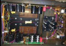
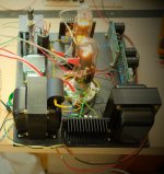
The 211 circuit is unknown to me, it was build 25 yrs ago by a contact of mine who did not share the design, fitting a lot of his own commercial designs into my half built chassis that I ran out of talent finishing. Next time it is off the shelf I intend to do some more measuring to deduce the circuit and PS if can. It's a voltage doubler from a 450V tap using two 5u4GB valves to achieve the 1000V B+. The driver valve is a 6c45, and it runs through an interstage transformer into the 211 (Lundahl LL1660 I think)
The PS has 2 Lundhahl 1673/10H Chokes, and there are also 3 vintage oil filled chokes used in the rest of the power supply - two I think in the driver power supply coming off half the doubler circuit. You can see a lot of the topology in the attached photos.
The idea of a choke to improve the sound quality of the heater circuit is also interesting, I had looked at these before in a moment of distraction but had sort of thought that at only 10.5 AC there was not enough voltage to be able to get to 10V DC with a choke? Then I read a few discussions whereby AC heating was stated as providing superior SQ, hence the post.
Attachments

In order to consider a Coleman Filament supply I assume I need an additional higher voltage transformer to power this, not being able to simply use the 10.5 AC tap in existence?Many folk are still conflating summing, which is linear (no new frequencies), with modulation (new frequencies generated). Mathematically, one is addition, the other multiplication. But I guess it doesn't really matter, except to understand the mechanism.
One issue not yet touched on is isolation from mains noises. The OP's situation doesn't look as if he has space for any heroic solutions, but LC filtering at 3R impedances would be heroically large. The best possible solution, a Coleman type regulator, needs voltage overhead, making it large too. Nothing is easy.
Would the OP be willing to outboard a Coleman filament supply?
All good fortune,
Chris
Better wait for Rod to comment on voltage overhead required, but you can research the new MOSFET switching active rectifier bridges, which have very low loss. See, for example:
https://www.diyaudio.com/community/...dc-5a-filament-supply-211-845-814-813.384820/
All good fortune,
Chris
https://www.diyaudio.com/community/...dc-5a-filament-supply-211-845-814-813.384820/
All good fortune,
Chris
One of the problems of filament DC is rectification. All SS rectifiers (as opposed to tube rectifiers) are noisy. Diode switching noise is not the only problem - there is also transformer ringing due to abrupt current cutoff at diode's forward voltage. Diodes with lowest forward voltage and slow switching are antique Ge things, but these deteriorate with time, and one have to check 30-50 of them to find a marginally usable pair. Rectifiers using controller-driven MOSFETs have zero forward voltage (very good!), but controllers are designed for capacitor input supplies, which is bad because capacitor input filters cause gross distortion of transformer current waveform. Intractable problem.
Ahh, yooze an engineer. (I'm not!) Your 'speech' was pretty unassuming and a bit hard to judge where you were coming from so I felt cautious about egging you on.
By Rod's general info sheet, you want a minimum of 3.5VDC for the Coleman reg. - Nominal 4.2VDC (and Max 7.)
This is where I was interested in your secondary's current capability as for a bridge rectified output for 3.25A I think you'd want it rated for something just under 5.5A at least. (I divide by .62 as from Hammond's recommendations)
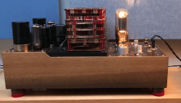
It's nice to see all the room you have in there though. From the picture it looks like you could fit an R-core or toroidal power transformer quite easily.
I do agree that Rod's regulator is a very good way to do it (they're on heatsinks in the 211 breadboard pic below), but I have a thing about people being dissuaded from checking things out for themselves so had to chime in. Once you've got it off the shelf and if you have the time, I still think it's worth trying before you go to something more sophisticated.
By Rod's general info sheet, you want a minimum of 3.5VDC for the Coleman reg. - Nominal 4.2VDC (and Max 7.)
This is where I was interested in your secondary's current capability as for a bridge rectified output for 3.25A I think you'd want it rated for something just under 5.5A at least. (I divide by .62 as from Hammond's recommendations)
It's nice to see all the room you have in there though. From the picture it looks like you could fit an R-core or toroidal power transformer quite easily.
I do agree that Rod's regulator is a very good way to do it (they're on heatsinks in the 211 breadboard pic below), but I have a thing about people being dissuaded from checking things out for themselves so had to chime in. Once you've got it off the shelf and if you have the time, I still think it's worth trying before you go to something more sophisticated.
Attachments
Last edited:
- Home
- Amplifiers
- Tubes / Valves
- AC Heater for better Sound quality? Waste of time or worth a try