That's a good point, but filament's fundamental frequency is normally nulled out by hum bucking pot, whereas second harmonic cannot be easily bucked.sser2,
The proof is when you have the opportunity to use an HP 3585 spectrum analyzer, one of the 2 best analog spectrum analyzers that cover the audio frequency range (The Tektronix 7L5 analog spectrum analyzer was the other world class analog spectrum analyzer for audio).
Tests on various AC powered filaments, using spectrum analyzers does very easily, and very clearly show the intermodulation of:
2 times the power mains frequency on a single note, and all its natural harmonics, and multiple instruments too,
with their fundamentals and natural harmonics.
The key to the proof is that it is not 1 times the power mains frequency, it is 2 times the power mains frequency.
There are no 1 times fundamental power mains frequency upper and lower sidebands on the musical notes; instead they are 2 times the fundamental power mains frequency: upper and lower sidebands on all the musical notes, and on all the natural harmonics.
By natural harmonics, I mean the harmonics that are naturally produced by musical instruments.
They have harmonics already; no recording and no playback systems need to apply their own distortions, the harmonics are already there from the musical instruments themselves.
Changing the DHT filaments from AC powered to DC powered makes those sidebands go away.
That shows that the 2X power mains frequency was not caused by the ripple on the B+.
Need more proof, do it yourself and see.
Good luck coming within 100 miles of either an HP 3585 or a Tektronix 7L5 spectrum analyzer; but if you find a location that has one, be sure to bring your Left channel AC powered DHT, and your right channel DC powered DHT. Ha! . . . or, crossing the ocean to Japan Hi!
No microphones, no preamps, no amplifiers, no headphones, and no loudspeakers, even if they are perfect.
The instruments already have their own harmonics, but generally do not already have their own IMD products.
IMD requires 2 separate frequencies at the same time, in order to produce the 2nd order and the 3rd order IMD products.
Some notes from S. Bench and D. Nizhegorodov :
https://diyaudioprojects.com/mirror/members.aol.com/sbench/humbal.html
https://www.dmitrynizh.com/filament-ac-freq.htm
All good fortune,
Chris
https://diyaudioprojects.com/mirror/members.aol.com/sbench/humbal.html
https://www.dmitrynizh.com/filament-ac-freq.htm
All good fortune,
Chris
I have owned two HP 3585's. Both died from the same cause with no cure. The HP 3585 was one of the first pieces of HP test equipment that used their own proprietary SOS (Silicon On Saphire) microprocessor chips. The SOS process was faster than conventional CMOS, but the chips didn't live long. The HP8903A audio analyzer also uses a SOS chip. I have repaired my 8903A three times including when I bought it dead for $100 over 20 years ago. Fortunately, I have a spare CPU board.The proof is when you have the opportunity to use an HP 3585 spectrum analyzer, one of the 2 best analog spectrum analyzers that cover the audio frequency range (The Tektronix 7L5 analog spectrum analyzer was the other world class analog spectrum analyzer for audio).
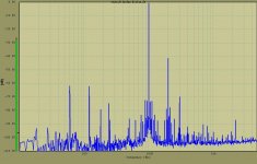
Depending on how the AC filament is wired you may or may not see odd harmonics of the line frequency in the IMD sidebands. This picture from almost 20 years ago shows 60 Hz, 120 Hz, 180Hz, 240 Hz, 360 Hz and 480 Hz sidebands around the 1 KHz tone on the 845SE proto at 10 watts of output. There is also plenty of 60 Hz and it's harmonics as this was done on the Tubelab breadboarding system with AC heating. Some of the line frequency and other low level crud was later determined to be from the 21 inch CRT monitor as it remains when all power supplies are switched off and unplugged from the wall. When setting up a test system like this I use a small Lepai solid state amp running from a battery pack as the test amp to eliminate line noise and ground loops. Once I get the expected results, I can insert the real amp to be tested.
Attachments

Two more questions: How audible are power line frequency x signal frequency intermodulations at -70dB (assuming them to be within the critical band)? And, does a DC voltage gradient across the cathode surface itself cause any non-linearity?
All good fortune,
Chris
All good fortune,
Chris
Hi Chris,
Look at the noise level in your listening area, subtract that from your maximum SPL. That is your dynamic range at best at full power with probably some clipping. If the hum is below your noise floor it will be very difficult to detect. It is really that simple.
Good question, I don't know, never worried about it since normal distortion is quite high anyway. It would probably also depend on the tube and it's quality.
-Chris
Some of you are missing the point.
Suppose you use AC filaments on a SE 2A3 DHT amplifier.
The amplifier has a perfect no-ripple B+.
You have a really good 2A3, and the AC balance pot is adjusted to get the hum to less than 100uV (0.1 mV).
Each end of the filament is going up and down by 1.25VAC, which is + 1.767V, and - 1.767V Peak.
There is no music applied to the amplifier, and . . . All is quiet.
Good.
Then, you apply a loud musical note, and the driver tube brings the 2A3 grid to within 1V of the space charge.
But just then, one end of the filament goes up by 1.767V.
It modulates the plate current. Then, the other end of the filament goes up by 1.767V, and that modulates the plate current again.
That is an easy to see, and easy to hear intermodulation on each musical note.
The intermodulation rate is at 2 X the power mains frequency.
Done. Cacophony.
Even if the music signal is at a lower level, the power mains 2 X intermodulation occurs.
At what level can you hear it is up to you, your ears, your system, your room, etc.
Think of a special hot filament that has a constant voltage along the wire. The field about it is the same all along the wire.
The grid "sees" a constant field from the filament to the grid.
Now, put AC across the filament, and the field along the filament is Not a constant voltage with respect to the grid voltage. But the voltage along the filament is changing at the AC rate. That modulates the plate current at 2 X the power mains frequency.
It is important to note, that although the average voltage of the field from the filament is relatively constant,
it is exactly constant 2 X during a cycle - at each zero crossing of the AC.
But at the other extremes, one end of the filament is at -1.767V, and the other end of the filament is +1.767V, and at those times, the center of the filament (and only the center) are at 0 Volts.
Now, put DC across the filament, and although the field is not a constant voltage along the filament,
at each point along the filament, the voltage is constant to the portion of the grid that is near it.
There is No modulation of the plate current.
If you can not understand that, it is OK.
Very few can get that concept.
An amplifier can distort music tones, both harmonic distortion and intermodulation distortion.
But those distortions originate and are related to the original music notes.
Note: your ear has the same harmonic and intermodulation distortions, when the sound intensity is loud.
The AC filament intermodulation distortion of a DHT has frequencies that are Not related to any of the original music tones.
Your ear does not have this kind of distortion (you are not applying an electrical signal from the power mains to your ear's nerves are you?)
Last edited:
That description is self-contradictory. It says that hum can be nulled out, but hum in the presence of signal cannot be nulled out. It also doesn't describe a modulation, but instead a summing. The better model is to say that an ideal (perfectly linear) valve has no inter-modulation and sums linearly, meaning no new frequency components. Real (non-ideal) valves inter-modulate (some) and generate new frequency components. (Largely second order which can be summed out by paralleling opposites or feeding differential-input loads, like push-pull OPTS, but that's a separate issue.)
The question of possible (or not!) non-linearity caused by a DC voltage gradient across the cathode is trickier. Framed another way, does grid-cathode voltage simply average, across a non-unipotential cathode? Or put another way, how constant is the zero signal average maintained (dynamically) over signal excursions?
All good fortune,
Chris
I don't see any principal difference between IMD from 2H of filament hum and IMD from two tones fed into amplifier's input. Why worry about filament intermodulating all music tones and not worry about tuba intermodulating all other instruments of the orchestra?
It is simple and straightforward. If an amplifier has high IMD, it will intermodulate filament hum with music tones, as well as different music tones with each other in all possible combinations. If an amplifier has low IMD, AC filament residual hum will be just that, residual hum, without screwing up music tones. It doesn't really matter where different frequencies are coming from - grid input or filament hum.
The solution therefore is not clumsy DC filament regulators with their set of problems, but rather reduction of amplifier distortion. PP instead of SE, for example.
Member
Joined 2009
Paid Member
Anybody tried one of those ‘electronic tansformer’ 12V bulb supplies? There were folk using them (slightly modified) as heater supplies, they provide a low cost high frequency a.c. Heating option.
I don't think it has to be self-contradictory. Isn't the point that the setting of the AC balance pot that nulls out the hum in the quiescent state (i.e. with some specific, fixed DC voltage on the grid) will be different from the setting that would be needed on the AC balance pot for some different voltage on the grid? And so as the music causes the grid voltage to undergo excursions around its quiescent value, so there will be a modulation of the musical signal by the AC heater voltage.That description is self-contradictory. It says that hum can be nulled out, but hum in the presence of signal cannot be nulled out.
Yes, that's exactly the case..Isn't the point that the setting of the AC balance pot that nulls out the hum in the quiescent state (i.e. with some specific, fixed DC voltage on the grid) will be different from the setting that would be needed on the AC balance pot for some different voltage on the grid?
The humpot attempts to minimise the Line frequency and its harmonics at idle, by locating the best triode-curve symmetry around the operating point. With a large grid signal applied, the symmetry breaks down, and the IMD appears in force.
The "triode curves" being swept by AC-filament voltages are not the usual data-sheet ones though, because the anode-to-cathode voltage is being substantially modulated at the same time as the grid-to-cathode - quite unlike the case of a music signal input.
It is completely different - as explained in the post above this one.It doesn't really matter where different frequencies are coming from - grid input or filament hum.
The statements made by 6A3sUMMER are correct from an engineering point of view. There will be measurable line frequency related sidebands generated whenever AC heating on a DHT is used. They will always be dissonant (non musically related) with respect to the music. They can be nulled at to some degree, but as he explained, they will rise as more and more of the available grid swing is used by higher level signals. Often these IMD products are masked by the music, so they are not heard. Whether these "by products" of the amplification process are audible, annoying, or even part of the "DHT sound" is up to the individual user. In my case my Yamaha NS-10M Studio monitors have very little response at 60 Hz, and 120 Hz is still a few dB down from their 87 dB sensitivity so none of the -70 and below stuff gets heard, but it can lead to listener fatigue. There are several other variables also present. One of my early TSE prototypes sounded good on my NS-10's but particularly nasty when connected to some 106dB Lowther based horns with active subwoofers. This was traced to line related ripple on the main B+ supply.
Every DHT amp I have built since my original experiments 20 years ago uses DC heating. I found that low noise active regulation works better than CRC filtering unless MONSTER caps are used due to the presence of higher order harmonics of the line frequency in the CRC filter. Huge caps create their own issues due to the short high current pulses involved.
Every DHT amp I have built since my original experiments 20 years ago uses DC heating. I found that low noise active regulation works better than CRC filtering unless MONSTER caps are used due to the presence of higher order harmonics of the line frequency in the CRC filter. Huge caps create their own issues due to the short high current pulses involved.
My opinion. Properly designed you shouldn't have discernable hum modulation when AC is used on the outputs only. This makes sense because while the current is high and the transconductance is low in the final stage. If you use AC on the previous gain stages - well. That's your choice but you will run into these problems.
It makes zero difference to the filaments whether you are using DC or Ac at the proper voltage. If you are suffering tube burnout, the filament voltage is simply too high. Easily checked with an accurate voltmeter, no excuses for this. The one thing I will say is that high current is involved, conversion to DC will cause excessive heat generation and high ripple current in the filter caps. Relax the size of the capacitors used, use an electronic regulator which will definitely run hot as well. Some input ripple will actually be a benefit as you aren't creating higher harmonics and you are reducing the hot switching current in your rectifiers (look that up). Okay, now for minimal benefit (if any real benefit) you have created a real reliability issue and energy loss. Tube heaters and filaments were designed to handle normal AC line variations, battery type tubes (2.5 volt and similar) are rather more critical. Still, modern line variations are not nearly as bad as they were in the past and may often be okay. You can design an AC regulator for the primary of the filament transformer. Look at the capstan motor circuit of a Revox A-77 for how to do this. I'm suggesting the primary circuit to keep the current and heat to a minimum. Just be aware you are working on the AC line and protect the circuit and yourself appropriately, use an isolation transformer when working on these circuits. Once it is running, just insulate any energized part you could possibly come into contact with.
Really, you just have to look at your hum levels and see it there isn't a design issue making it worse. Many older radios used AC current in the output stages and did not suffer from hum. So you can do this and it just makes more sense (which is why they did it back in time). Otherwise you are merely pursuing specmanship for bragging rights. Great, what does that actually buy you? It buys you maintenance issues and hotter running transformers. This is something that should be engineered, you don't just smile and throw stuff at the issue, think about what you are doing. If you really want to chase numbers that's fine. Just be honest about it and advise others in a balanced way. Every approach has a balance of positives and negatives, try and assess what makes sense. That's called engineering.
-Chris
Without proof, whether it is same or different, is just an opinion.It is completely different - as explained in the post above this one.
Do you have an explanation for how AC heating can operate without modulating the anode-cathode voltage?
If not, the mechanism of distortion is different from a simple grid input.
If not, the mechanism of distortion is different from a simple grid input.
Hi Rod,
Depends on the thermal time constant of the filament. Potential differences average out. So that depends on tube construction.
Depends on the thermal time constant of the filament. Potential differences average out. So that depends on tube construction.
It's not about the heating effect...
With the hum-pot connected to ground (or an Rk + Ck cathode bias network), the two ends of the filament ride up and down with the line frequency, in antiphase. That means the anode-cathode voltage is modulating at the two ends.
The potential may average out on a thermal timescale, but the instantaneous emissive anode current depends on the instantaneous voltages, at each point.
And because the curves are not symmetrical (above and below the idle operating point) the differences in current do not fully cancel. This does not happen with a grid signal, and DC heating - it's a distortion mechanism unique to AC heating.
The grid-to-cathode voltage is also modulated by AC-heating, but that does happen with a music signal at the grid - naturally.
Hi Rod,
I agree. That's why I Said it depends on tube construction. The effect may be below the noise floor, in other words, not audible. Or it may be audible. Don't forget that you have low transconductance and a step-down transformer between the tube and speaker.
All I'm saying it that it depends on a few things. Obviously how you've done your hum balance can come into play as well. So it becomes an engineering question, not something you can just assume to be true or false. You also have to balance the other factors I mentioned.
- Home
- Amplifiers
- Tubes / Valves
- AC Heater for better Sound quality? Waste of time or worth a try