@Prasi:
Thanks for the gerber files!
@European diy guys: I ordered 10 boards and can sell 6 boards for the same price I paid
If someone is interested, contact me via pm.
Thanks for the gerber files!
@European diy guys: I ordered 10 boards and can sell 6 boards for the same price I paid
If someone is interested, contact me via pm.
I didn't see the updated Prasi AB 100 gerbers, link?
How do they differ from the ones originally posted?
How do they differ from the ones originally posted?
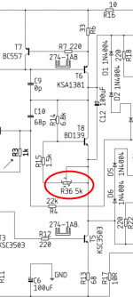
Hey Prasi . Before switching the boards on the first time , on your layout , am I correct in thinking that trimpot screw must be turned all the way counter-clockwise for minimum bias setting ?
Quiescent current can be set to 80mA (measured over fuse holder with fuse removed) , or 20mA over 1e emitter resistor ?
Quiescent current can be set to 80mA (measured over fuse holder with fuse removed) , or 20mA over 1e emitter resistor ?
I suggest using an ohmmeter to measure the resistance between pin1 and pin3 of the R36 trimmer potentiometer, after it has been stuffed and soldered to the PCB. Whichever setting gives the LARGEST resistance from pin1 to pin3, is the safest (lowest bias) starting point for bias adjustment. Measure it twice and reverse the probes for measurement #2. Patiently wait 30 seconds to allow the reading to settle.
_
_
Attachments
Last edited:
Hey Prasi .
Quiescent current can be set to 80mA (measured over fuse holder with fuse removed) , or 20mA over 1e emitter resistor ?
Hi Fredeb, 20mA measured over any one of the 1R resistor would be more convenient. 20mV delta V. Use bulb tester for initial 'firing-up'🙂
Last edited:
Thank you kindly Prasi . Now I need to find heatsinks . Perhaps I'll try a temporary solution like aluminium angle extrusion , just to see if all is functioning as it should . Excited ! 😊
WOW!
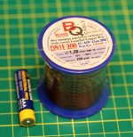
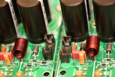
inductor can be 10-12 turns wound on AAA cell with 1.2 mm magnet wire/ enameled wire

Attachments
Last edited:
progress
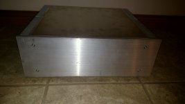
Managed to gain a little ground.
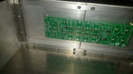
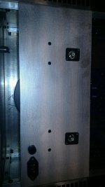
Got my boards mounted to the heatsinks and the front face mounted as well.
At last count that leaves 22 more holes to drill and tap.
Slow work takes time.
Managed to gain a little ground.
Got my boards mounted to the heatsinks and the front face mounted as well.
At last count that leaves 22 more holes to drill and tap.
Slow work takes time.
Attachments
 your amplifier diy progress looks good - I wish you a successful finishing and testing phase!
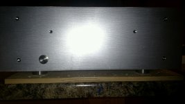

Looking amazing flamethrower1 . Well done !
I finally have one channel biased and have been listening to one channel plugged into an old 6x9 driver lying on it's back . I'm going to assemble 6 boards . A pair for my dad , a pair for my friend and a pair for myself . May try some different parts on the last 2 boards to hear the difference .
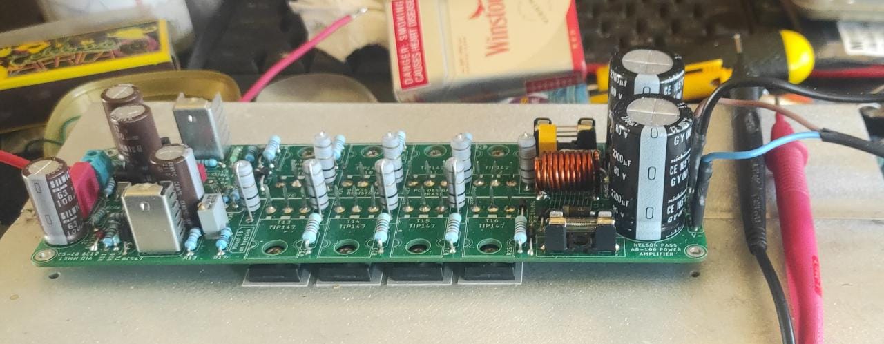
I have an off board PSU - will draw a schematic of what I did there . I have bias set to ~18mA per output device . Offset seems.to be lowest at that point . Offset is hovering around 2.5mV . Input devices.are well.matched .
I finally have one channel biased and have been listening to one channel plugged into an old 6x9 driver lying on it's back . I'm going to assemble 6 boards . A pair for my dad , a pair for my friend and a pair for myself . May try some different parts on the last 2 boards to hear the difference .
I have an off board PSU - will draw a schematic of what I did there . I have bias set to ~18mA per output device . Offset seems.to be lowest at that point . Offset is hovering around 2.5mV . Input devices.are well.matched .
Last edited:
Ok, after reading that, it does not come across as intended.
What I really meant was, nice work and thank you
What I really meant was, nice work and thank you

I decided to build another amp.
Offer pcb / part kit
https://www.diyaudio.com/forums/swap-meet/376307-pass-ab-100-pcb-kit.html#post6767065
Offer pcb / part kit
https://www.diyaudio.com/forums/swap-meet/376307-pass-ab-100-pcb-kit.html#post6767065
Started populating my boards and have come across a question.
The BOM calls out 220 for R35.
Board calls out 10 (optional) schematic also calls out 10.
Which is correct?
The BOM calls out 220 for R35.
Board calls out 10 (optional) schematic also calls out 10.
Which is correct?
- Home
- Amplifiers
- Pass Labs
- AB100 Class AB Power Amplifier