Here are some info files. for the sch and stuffing guide posted. hope its the same thing you want.
Attachments

Hi Prasi,
Many thanks I was using these gerbers you had made
AB100 Class AB Power Amplifier
Post 812
using the 4 caps.
Thank you so much this would be great.
quick question since you asked have you updated the pcb since then?
Many thanks I was using these gerbers you had made
AB100 Class AB Power Amplifier
Post 812
using the 4 caps.
Thank you so much this would be great.
quick question since you asked have you updated the pcb since then?
Here are some info files. for the sch and stuffing guide posted. hope its the same thing you want.
hello jk556,
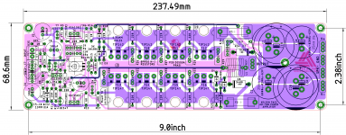
here are the updated gerbers as per the above quoted post.
no major changes except option for 2 big 35 mm caps instead of 4 smaller caps and doubling up of traces at some places.
Attachments


Hi Prasi,
Really awesome thank you so much, you are really helpful.
Just a quick question in the new schematic it just looks like you might be missing a via where the J3 connects to ground on the right hand side. See attached.
Im assuming the colors indicate top or bottom copper.
Really awesome thank you so much, you are really helpful.
Just a quick question in the new schematic it just looks like you might be missing a via where the J3 connects to ground on the right hand side. See attached.
Im assuming the colors indicate top or bottom copper.
Attachments

Prasi, thanks for sharing the hole drilling info will come in handy for drilling my heatsinks.
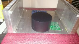
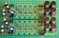
A little progress.
First time building an amp chassis.
Makes any more easier though.
A couple of questions for those who have ventured down this path before.
On the PSU why is this amp not required to have CRC filtering?
I mean I have seen a couple of builds that have a cap bank prior to the amp boards with all of the caps just jumpered together.
Sorry if it is a naïve question, just wondering.
Also, would a 38 volt tranny be to much with the standard BOM?
Attachments
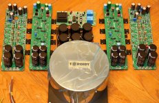
@ Flamethrower
the chassis is looking good. I would consider some ventilation for the base plate
..dB
the chassis is looking good. I would consider some ventilation for the base plate
..dB
A little progress.
First time building an amp chassis.
Makes any more easier though.
A couple of questions for those who have ventured down this path before.
On the PSU why is this amp not required to have CRC filtering?
I mean I have seen a couple of builds that have a cap bank prior to the amp boards with all of the caps just jumpered together.
Sorry if it is a naïve question, just wondering.
Also, would a 38 volt tranny be to much with the standard BOM?
As far as I know with my limited knowledge, it is because while a Class A amplifier has a constant current consumption, Class AB amplifiers current consumption depends on dynamic spikes in music, so it isn't so constant. Moreover, serial resistances between PS capacitors will increase internal resistance of PS, which isn't good. It would decrease the damping factor of the amplifier.
I don't know if I was understandable.
I hope at least I'm right.
I like your sturdy chassis!
There is nothing stopping one from installing a couple more caps off board , especially if your transformer doesn't have enough oomph . Use low ESR , low capacitance caps to avoid series resistance .
I think ?
I think ?
There is nothing stopping one from installing a couple more caps off board
Douglas Self warns against doing this in a sloppy & haphazard way. He even gives it a name: "Distortion Five: Rail Decoupling Distortion". It's in his power amplifier book (all editions).
Google gives you a general idea of what he has to say, link
Douglas Self warns against doing this in a sloppy & haphazard way. He even gives it a name: "Distortion Five: Rail Decoupling Distortion". It's in his power amplifier book (all editions).
Google gives you a general idea of what he has to say, link
Thank you Mark .
Doug Self :
"5. Non-linearity caused by large rail-decoupling capacitors feeding the distorted signals on the supply lines into the signal ground . This seems to be the reason many amplifiers have rising THD at low frequencies. Examining one commercial amplifier kit, I found that rerouting the decoupler ground-return reduced THD at 20 Hz by a factor of three."
I am interested in learning what the right and wrong way of routing the decoupler ground-return is .
I'll be using the Prasi board with 2 caps . My thoughts were that to add another 2 or 4 caps off-board , after the rectifier would not be a problem . Perhaps 2x 6800uF on the boards , and 2x CR of 6800uF and 1e in series off-board .
Prasi also provides the option of a 10e ground-lift at the input on his layout , which I guess may also help with this problem .
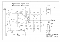
Attached Prasi layout schematic as reference .
Attachments

Last edited:
I omitted to add that a correction has been made since this schematic , changing R3 from 100e to 1k .
AB100 Class AB Power Amplifier
AB100 Class AB Power Amplifier
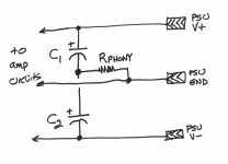
One "trick" you can do to ensure better than average rail decoupler layout, is to put a phony baloney 1 ohm resistor in your schematic and in your PCB layout. This resistor guarantees that the rail decouplers are connected to each other "upstream" of their common connection to power supply ground.
Then when you stuff the board, you can install whatever resistance you wish into that footprint. 1 ohms? sure! 0.1 ohms? sure! Jumper wire (0.0 ohms)? sure! You'll still have a better than average layout topology.
_
Then when you stuff the board, you can install whatever resistance you wish into that footprint. 1 ohms? sure! 0.1 ohms? sure! Jumper wire (0.0 ohms)? sure! You'll still have a better than average layout topology.
_
Attachments
Thank you Mark. I don't understand it , but I will take your word for it .
Very interesting , I have seen this resistor being used before , and did wonder what the purpose was .
Very interesting , I have seen this resistor being used before , and did wonder what the purpose was .
- Home
- Amplifiers
- Pass Labs
- AB100 Class AB Power Amplifier