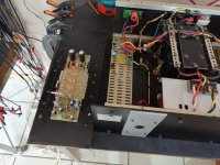
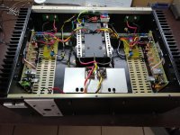
"pragtig". Probably all I can remember from the time I lived in the Vaal. Really well executed build Jan, glad to hear it sounds as good..dB
I would use some resistors or inductors between those power bank capacitors as a CRC or CLC set up.
Thanks all !!
Gaborbela, there is no need to change anything, amp is dead quiet, no hum or buzz.🙂
Gaborbela, there is no need to change anything, amp is dead quiet, no hum or buzz.🙂
Congrats Jan,
You have done a great job. I sure you will enjoy it for many years.
regards
prasi
You have done a great job. I sure you will enjoy it for many years.
regards
prasi
Thanks Prasi, it is on its way to my daughter a 1000km from here. Quite heavy as well, big 800 VA transformer, amp weighs 40kg. 😀
Could this Class A/B design be tweaked to an amp working as a power plant or mains AC regenerator to regenerate 230 VAC?
The rails should be about -+200 VDC I guess and output transistors should be able to handle that voltage. Input should be a fairly clean 50 Hz sinus (maybe digital generated). Then my clipped sine in my mains could be changed to a nice clean sinus with very low impedance I guess?
The rails should be about -+200 VDC I guess and output transistors should be able to handle that voltage. Input should be a fairly clean 50 Hz sinus (maybe digital generated). Then my clipped sine in my mains could be changed to a nice clean sinus with very low impedance I guess?
the mains has 230V RMS, so DC power supply will need + - 350-360V (taking into account the degree of loss and mains fluctuations)...this circuit does not meet such requirements - everything must be changed there - such an amplifier needs 1000V transistors and resistors and everything else
Last edited:
Yes, you are right +-350 VDC in rails.
I guess such transistors exist as it seems such re-generators are "just" class A/B amplifiers feed with a fairly clean sine input. Then output has to be DC-free and there should probably also be some regulation of the output voltage so it stayed steady at about 230 VAC.
I guess such transistors exist as it seems such re-generators are "just" class A/B amplifiers feed with a fairly clean sine input. Then output has to be DC-free and there should probably also be some regulation of the output voltage so it stayed steady at about 230 VAC.
But may be too much change......so it would be a completely different amp.....it is just....that it needs to be a class A/B.....and not A of course.....


Prasi, nope thanks, I'm oldskool ! Thanks again for your contributions with pcb layouts that keeps guy's like me out of trouble !😀😀
Nice work Jan!
I want to ask Mr.Pass.
Are the combination of 2sb1560+2sd2390 suitable for output in this amplifier?
I want to ask Mr.Pass.
Are the combination of 2sb1560+2sd2390 suitable for output in this amplifier?
Last edited:
Hi Guys,
First of all thanks to NP and Prasi for the design and PCB
I am planning on putting this together, but just had some quick questions. What should the values of L1 and R37 be?
Also at the position C7 should there be a film cap and the electrolytic over it? Also any ideas for good values of the fuses F1 &F2?
Have a transformer with 36V secondaries should five ~50VDC right? Or should go with a lower rail voltage? maybe 24V secondaries?
Thanks for the help
- Home
- Amplifiers
- Pass Labs
- AB100 Class AB Power Amplifier