Hi, used 2uf2 and 3uf3 caps at input ( even with 1uf you will have 7Hz cut off frequency) . For my first build i used 0,5R emitter resistors (two 1R parallel) and 0,235R for second one ( 2wo 0,47 R in parallel) to lover gain i changed R3 from 100R to 1K.
hello
i only matched the input transistors but can't tell how much it affects the dc offet - in my case it's approx. 10mV in both channels.
I use other output transistors (MJ11015/16) and they are from the factory at quite the same range judging by the bias voltage drop on individual emitter resistors.
but i don't know what is the parameter distribution of TIP series transistors in this regard.
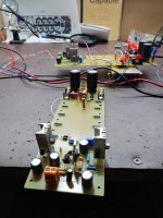
Amp ha been completed and it sings like crazy 😀
Everything worked even without test boards. No hum, dc offset 2mV and 10mV per channel.
Bias 40mA per transistor - runs cool.
no turn on/off thumps.
PSU - +- 45V 30 000Uf in each rail.
indicator diode foe each rail.
Transistors - ztx450,550,MJ340/350, mj11016/15.
0,5 ohm emitter resistors and base stopper divided-100R on PCB and 100 on transistor base pin.
I will measure later with scope and sound-card - now I am a little tired after amp hobby work 🙄
nice front panel, " angry villagers armed with pitchforks and torches" as mentioned by NP in first post. just had a look at your work. congrats!
I'm still waiting for some spares......🙁
ZUM911, are you still happy with your amp ?
Regards
Jan
ZUM911, are you still happy with your amp ?
Regards
Jan
Hi Jan,
I'm not using it as my main amp right now. I made it to drive the woofers in a bi-amp system and I'm still working on the speakers. I ran the amp for about a week after I built it and I thought it was quite musical.
I'm not using it as my main amp right now. I made it to drive the woofers in a bi-amp system and I'm still working on the speakers. I ran the amp for about a week after I built it and I thought it was quite musical.
Thanks for the feedback ZUM.
Osscar, just a question, when I look at the schematic that you have posted of your build then I see that you have used slightly different values for the resitors. R1- 470R, R14-5.6K, R15-1K. Is there a specific reason for the changes ?
Regards
Jan
Osscar, just a question, when I look at the schematic that you have posted of your build then I see that you have used slightly different values for the resitors. R1- 470R, R14-5.6K, R15-1K. Is there a specific reason for the changes ?
Regards
Jan
no there is no special reason for that, i had such parts - so i use them
Me too.

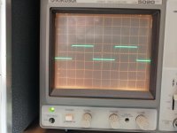
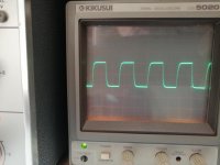
Got a chance to finish the boards. I have installed just 1 pair of OP transistors for testing. Running on +-40VDC. Bias is set to 20mA, DC offset on boards is 9-12mV and 15-18mV. I have just HFE matched the input transistors. Square wave looks good, 1kHz and 20kHz. I have used all die original resistor values except R3 is 1K.Sound is good, high frequencies are more subtle, sounds like more H2. I think I need a little more gain, maybe change R3 to 470R. I will first test with a decent preamp and not using a phone as source. What will the advantage be in changing the emittor resistors from 1R to 0.47R ? Thank you Mr Pass and Osscar for the help and thanks Prasi for the great pcb layout !🙂
Attachments
HI,
Looks very good, no ringing etc. Yes , you can adjust gain. According to D.SELF's book - the smaller Re - the better, but you need a greater bias current and a greater risk of burning something usually i see that all amplifiers use 0.22R or 0.33R or 0.47R.
Regarding FFT - according to LT spice - with TIPs you have more 3H, but with MJ - more 2H..i cant explain this - i don't know how accurate are the different transistor models..best way would be to measure but my EMU usb card doesn't work with win 10...so i need to buy a newer one - Focusrite for example.
Looks very good, no ringing etc. Yes , you can adjust gain. According to D.SELF's book - the smaller Re - the better, but you need a greater bias current and a greater risk of burning something
usually i see that all amplifiers use 0.22R or 0.33R or 0.47R.Regarding FFT - according to LT spice - with TIPs you have more 3H, but with MJ - more 2H..i cant explain this - i don't know how accurate are the different transistor models..best way would be to measure but my EMU usb card doesn't work with win 10...so i need to buy a newer one - Focusrite for example.
in any case with more output transistors the THD will be lower.
if you have space on PCB - you can add 1ohm parallel to each - just drill holes.
if you have space on PCB - you can add 1ohm parallel to each - just drill holes.
Last edited:
osscar, thanks, Am I correct when I say the lower the Re, the more the output power ? or does it change the sound as well ? yes, I have used MJE's and I'm using 10uf input cap for testing purposes. Signal transistors are BC547,557.
Last edited:
not so much output power - but more each output transistor bias - with 1R N.Pass has specified approx. 20mA per transistor.
With one pair and 0.235R I set 100mA per transistor and with 2 pairs and 0.5R - 50mA on each. with these settings amps run cool and sounds nice.
With one pair and 0.235R I set 100mA per transistor and with 2 pairs and 0.5R - 50mA on each. with these settings amps run cool and sounds nice.
Ok thanks, think I will get 0.47R Re's, now I first have to wait for the machined heatsinks. Thanks a lot !😉😀
Regards
Jab
Regards
Jab
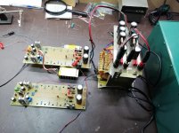
Well I have tested both boards today for an hour or two on idling with input shorted. 9-11mV dc offset, bias very stable at 20mV. It might be that the caps have reformed a bit but the sound is great, I'm sticking with 1R emittor resistors for now, can always change if needed. I might use another transformer with +-50V rails, but I dont think it is necessary. A very happy chappy I am.😀
Attachments
- Home
- Amplifiers
- Pass Labs
- AB100 Class AB Power Amplifier