Hey,
How are the measurements going? Have you guys measured the ODA front-to-back a la Nwavguy?
Also, adydula's post mentioned you:
O2 AMP + ODAC - Page 234
How are the measurements going? Have you guys measured the ODA front-to-back a la Nwavguy?
Also, adydula's post mentioned you:
O2 AMP + ODAC - Page 234
I know the first round were completed and AGDR made some adjustments to the ODA and it was sent back for a second test, I don't think the second round has been done yet. The person doing this is volunteering his time and is a pretty busy person, I hope this will be done soon!!
I am sure AGDR will comment and post the findings when they are completed.
Alex
I am sure AGDR will comment and post the findings when they are completed.
Alex
Darkwizzie,
I got a response from the person doing the measurements, he is getting close to performing the second round in the near future, stay tuned!
Alex
I got a response from the person doing the measurements, he is getting close to performing the second round in the near future, stay tuned!
Alex
Darkwizzie,
I got a response from the person doing the measurements, he is getting close to performing the second round in the near future, stay tuned!
Alex
That is great news! The fellow doing the dScope measurements said that his camera batteries died during all the tests after the initial 15R load and he didn't discover it until the end. So I haven't seen the results with other loads myself. He has bought a new camera for the next round of testing he said. This will be interesting! 15R should be the worst case scenario though.
Equally interesting will be that THD+N test on the O2 headphone amp with the volume pot in the middle, a test that NwAvGuy didn't do. Lets see if input impedance distortion is an issue with the O2.
Alex - I just tried replying to your PM but the system says your PM box is full. Time to delete a few! 🙂
Are there any pics of the completed amp in its case? Did I read correctly that not only is this a headphone amp, but can be used as a preamp for an external amplifier as well? I have been looking for something like this for a while now.
Are there any pics of the completed amp in its case? Did I read correctly that not only is this a headphone amp, but can be used as a preamp for an external amplifier as well? I have been looking for something like this for a while now.
Here are some pictures at the bottom of post #302. The cases come in several different colors - black, blue, green, red, silver (aluminum) and gold.
The ODA unfortunately wouldn't be a good pre-amp. It is a headphone power amp.
If that is the case, why the added complexity of a set of preamp outs on the front? Why wouldn't it be a good preamp, not enough power?
If that is the case, why the added complexity of a set of preamp outs on the front? Why wouldn't it be a good preamp, not enough power?
Whoops, I think that I mis-read your post - sorry about that! I was thinking that you were considering using it only as a pre-amp, in which case it would be overkill with the additional headphone amp section. But on re-read I see that you are thinking of both, headphone amp plus pre-amp, so yep that is exactly what the ODA does. 🙂 I added that pre-amp output because NwAvGuy had so many requests in his blog comments for an added pre-amp out on his ODA or the next version of his O2 amp.
In the ODA I have that front panel pre-amp out jack set up so it can be wired up in several ways. It can be wired in parallel across the rear RCA jack or front 3.5mm jack so that any signal going in those also goes out the pre-amp out jack.
I also have a place for a dual op-amp just for the pre-amp section. That chip can be set up for a gain of 1 (current buffer) or with a voltage gain. So another way to wire things is have the signal coming in from the rear RCA jack or front 3.5mm jack first go to the pre-amp buffer, then out to the pre-amp out jack. That way whatever is plugged into the pre-amp out won't load the input signal.
The chip I'm currently suggesting in the BOM for pre-amp is just the surface mount version of the NJM4556A chips, the same one used in the amp's headphone outputs. The NJM4556A can easily drive the capacitance in any length of RCA cable and pre-amp input. Other op-amps can be used, but most others can only drive up to 100pF without having an output resistor. I've included a place for an output resistor on the pre-amp outputs for that reason. But the NJM4556A wouldn't need any output resistor (a "zero ohm" jumper resistor is used).
It would also be possible to wire it up so the pre-amp out comes off the output of the ODA gain stage or even the output going to the headphones, but those could have up to a 7.25Vrms swing which would be way to much for line-level audio.
Last edited:
Whoops, I think that I mis-read your post - sorry about that! I was thinking that you were considering using it only as a pre-amp, in which case it would be overkill with the additional headphone amp section. But on re-read I see that you are thinking of both, headphone amp plus pre-amp, so yep that is exactly what the ODA does. 🙂 I added that pre-amp output because NwAvGuy had so many requests in his blog comments for an added pre-amp out on his ODA or the next version of his O2 amp.
In the ODA I have that front panel pre-amp out jack set up so it can be wired up in several ways. It can be wired in parallel across the rear RCA jack or front 3.5mm jack so that any signal going in those also goes out the pre-amp out jack.
I also have a place for a dual op-amp just for the pre-amp section. That chip can be set up for a gain of 1 (current buffer) or with a voltage gain. So another way to wire things is have the signal coming in from the rear RCA jack or front 3.5mm jack first go to the pre-amp buffer, then out to the pre-amp out jack. That way whatever is plugged into the pre-amp out won't load the input signal.
The chip I'm currently suggesting in the BOM for pre-amp is just the surface mount version of the NJM4556A chips, the same one used in the amp's headphone outputs. The NJM4556A can easily drive the capacitance in any length of RCA cable and pre-amp input. Other op-amps can be used, but most others can only drive up to 100pF without having an output resistor. I've included a place for an output resistor on the pre-amp outputs for that reason. But the NJM4556A wouldn't need any output resistor (a "zero ohm" jumper resistor is used).
It would also be possible to wire it up so the pre-amp out comes off the output of the ODA gain stage or even the output going to the headphones, but those could have up to a 7.25Vrms swing which would be way to much for line-level audio.
Here is what I am hoping to do. I have a set of Sennheiser headphones (lower model, but man do they sound good) that when I run them on my iPhone, I have to have the volume at 75%. So, I want to be able to listen with nicer quality than the amp in the iPhone. Also, I am going to be building a chip amp that works best with a preamp.
So I am looking for a dual role amp for this purpose and this is the only one that I have found that fits that bill (without sacrificing something in the process). I have some soldering skill (through hole is fine for me), but have not tackled any surface mount work yet. Willing to try though. You mentioned needing a higher watt iron to do the work, why is this?
I posted on your Vendor thread (awaiting moderation) asking if you happen to sell a kit with all the parts (case would be nice, but not necessary, thought about building a nice wood case to match my furniture, my only concern is a heatsink for the rear of the unit).
Here is what I am hoping to do
Sounds good!🙂 What model of Senns? I can do the math and figure out what kind of votlage and current they require.
For really any of the soldering work, though-hole or surface mount, I would highly recommend at least an 80W temperature controlled soldering station. Then for the surface mount soldering also something equivalent to a Panvise 350:
PanaVise 350 Multi-Purpose Work Center: Bench Clamps: Amazon.com: Industrial & Scientific
You will wind up with either one hand holding the part with tweezers while the other melts solder on a pad to stick in the SMD part, or the iron in one hand and solder in the other for the other end of the SMD part. Either way that leaves a person one hand short to hold the board without a board vise of some kind.
Then the third essential thing for SMD is tweezers like these:
http://www.amazon.com/Vetus-Safe-Fine-Curved-Tweezers/dp/B00A9N5GUC
to hold the SMD part by the sides.
So with those things all you do is put a little solder on one SMD pad. Then heat it up and stick one end of the SMD part in while holding the part with the tweezers. You may need to re-heat it a couple of times to get the other end of the part linned up right on the pad. Let that cool for a minute then solder up the other end. Let that cool then go back to the first end and re-solder that to touch it up. And that is it! You will get the hang of it over time. A magnifying glass on a stand or swing arm is helpful too.
The chips are a little more nerve wracking. 🙂 Line them up on the pads with the tweezers, then with solder aready on the tip of the iron solder a pin on one corner of the chip. Then with a magnifying glass check the alignment of the other IC pins on their pads. They should be just exactly over the pads, not off to one side or the other. You will probably have to reheat that one corner pin a couple of times to get the pins lined up. then solder a pin on the other diagonal corner and check alignment of the pins againn with the magnifying glass. If all good you can either drag a small ball of solder across the pins, or if you have fine iron tip and fine solder actually solder up the pins one by one. I do the latter these days but I've been soldering for 40 years too - lots of practice. 🙂
You can definitely mount the board in any case you want, thanks to a good suggestion from dace earlier in the year to put holes on the corners of the board. But your are right, you still need to bolt a heatsink to the back for the voltage regulators. You can just bolt up a regular back panel then mount the whole thing in another case.
I'll send you a PM with some more information.
By far the most useful tool I've bought and used is a modified $25 aquarium vacuum pump sold on eBay for smd pick and place, plus bent nozzles of various sizes.
After buying a few pricey SMD tweezers I find myself using the vacuum pen all the time to solder smd parts. I even put a t piece into the vacuum line and apply vacuum using my foot giving me a very precise place and hold tool which works great for 0603 parts!
Sent from my iPad using Tapatalk
After buying a few pricey SMD tweezers I find myself using the vacuum pen all the time to solder smd parts. I even put a t piece into the vacuum line and apply vacuum using my foot giving me a very precise place and hold tool which works great for 0603 parts!
Sent from my iPad using Tapatalk
By far the most useful tool I've bought and used is a modified $25 aquarium vacuum pump sold on eBay for smd pick and place, plus bent nozzles of various sizes.
What a fantastic idea! I'll get one of those. 🙂
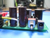
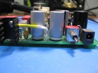
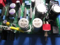
New 820uF, 50V, 25mm tall caps are in stock at Mouser
The new, shorter, 25mm tall 820uF 50V power supply filter caps for this project are finally in stock at Mouser as of two days ago.
I've just updated the BOM out at the Google Drive link in the first post in this thread. Up until now I've had these new caps listed in the BOM as an alternative in yellow background, until Mouser started stocking them.
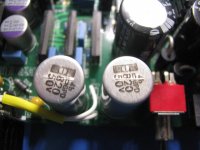
Photos below showing the old 30mm high caps (brown) vs the new 25mm high (silver). The negative lead on the new caps is denoted by that black bar on the top of the cap. All 4 filter caps are now 25mm tall, leaving lots of spacing to the top case slot for any future board additions there.
Mouser appears to have all the other "out of stock" stuff in now too: the 1K linear volume pot, the vertical RCA jacks, and the 24V coil relay.
The next round of dScope tests haven't been completed yet, but Mike says he may get time in the next few weeks. He was involved with a presentation at the RMAF show.
The new, shorter, 25mm tall 820uF 50V power supply filter caps for this project are finally in stock at Mouser as of two days ago.
I've just updated the BOM out at the Google Drive link in the first post in this thread. Up until now I've had these new caps listed in the BOM as an alternative in yellow background, until Mouser started stocking them.
Photos below showing the old 30mm high caps (brown) vs the new 25mm high (silver). The negative lead on the new caps is denoted by that black bar on the top of the cap. All 4 filter caps are now 25mm tall, leaving lots of spacing to the top case slot for any future board additions there.
Mouser appears to have all the other "out of stock" stuff in now too: the 1K linear volume pot, the vertical RCA jacks, and the 24V coil relay.
The next round of dScope tests haven't been completed yet, but Mike says he may get time in the next few weeks. He was involved with a presentation at the RMAF show.
Attachments
Mayflower is slowly working on the prototype ODA.
I have a question about caps. Some people say they make the sound better... I am skeptical. O2/Odac's performance is already transparent, I see better caps as an overkill kind of deal. Which isn't to say that's totally pointless. So, what are the "best" caps to use? You heard of the motherboard onboard marketing buzzwords? Nichicon, Ulna caps, blah blah.
I have a question about caps. Some people say they make the sound better... I am skeptical. O2/Odac's performance is already transparent, I see better caps as an overkill kind of deal. Which isn't to say that's totally pointless. So, what are the "best" caps to use? You heard of the motherboard onboard marketing buzzwords? Nichicon, Ulna caps, blah blah.
Mayflower is slowly working on the prototype ODA.
That is good news Mayflower is building up their ODA board. 🙂 I sent them a blank V2.1 board, the latest thing that was from the at-cost DIY PCB run here a couple of months ago.
As for caps, on the ODA the only thing special in any way about the main filter caps and bypass caps is being low ESR and a small size to fit in the case. Any brand will do for those as long as the capacitance & voltage rating is the same, the ESR is low and they fit. I used solid ogranic polymer for the bypass caps after the regulator just because they seem to provide the lowest ESR in the smallest size package these days.
As for caps in the O2 headamp, I've posted my thoughts on "modern" O2 part upgrades here a couple of months ago. Again brand isn't important, but in the case of the O2's main film coupling caps there is a 3.3uF film capacitor available now that is the same physical size as the 2.2uF on the O2 BOM. The substitution just drops the lower end of frequency response roll-off from "too low to hear" to "way to low to hear". lol. 😀 In other words, unlikely to hear any difference but why not since the higher uF caps exist.
Same for the O2 main power supply filter caps. As I've listed in that link some newer caps have come out since NwAvGuy posted his BOM that are even slightly lower in ESR and are the same physical size. They might help a little bit in reducing vreg input ripple with the O2's problem of the voltage regulators going into dropout with a 12Vac transformer and a heavy load. The thing that would help the most with O2 vreg dropout would be larger capacitance to reduce the amount of ripple, but even to this day I can't find any caps in that voltage & size can that are low ESR and greater than the 470uF in his original design.
Last edited:
B2-080 case blank panels sent into FPE - CAD files
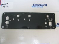
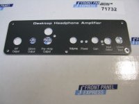
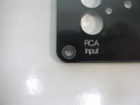
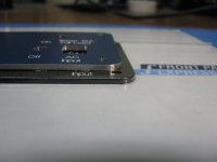
I've finally had an opportunity to try mailing the two blank panels that come with a Box Enclosures B4-080 case to Front Panel Express to use as the drilling stock. The finished panels arrived today. I'm happy to report the results are just excellent. The panels that come with the case have the edges color-anodized too and slightly rounded for a nice professional look. The aluminum stock that FPE would use normally is milled out of a larger sheet so the edges wind up as bare aluminum with a square, sharp edge.
The photos below show the panels as shipped, then a close up of an edge of the new panels (black panel and edge) vs. a blue panel from a previous run that used FPE's own stock and wound up with the bare aluminum edge. That isn't a scratch on the rear panel. They are still blister packed to the shipping cards here and there is small crease in the blister plastic.
The Front Panel Designer CAD files have to be modified to remove the five panel-to-case holes, since the blank panels from the case already have those drilled. I've posted the new CAD files out at the project Google Drive link. Under "panels" there is now a subfolder for using FPE's blank stock or mailing the B4-080 panels to FPE. When the panels are mailed the order number(s) from FPD just have to be written on the shipping box somewhere and/or included with the blank panels to match them up to the order.
The procedure for using the panels form the case is pretty simple. In the CAD program there is a checkbox under "file" -> "panel properties" that says "use customer provided material". Just check that and everything else stays the same. The panel color selection is ignored. The box has already been checked with the new CAD files. The origin also has to be specified in an email to FPE with the order numbers that FPD generates. In the case of these panels the origin is off-panel, since the corners are already rounded on the blank panels, at the intersection of the left edge and the bottom edge, and the blank panel oriented so the 5th mounting hole is at the bottom in the middle.
The one concern I had is how well the countersink around the lower left moutning hole, to break the anodization for a good electrical contact, would align given the pre-dilled panel hole. As can be seen in the 4th picture the alignment wound up being very good.
Attachments

Last edited:
That is good news Mayflower is building up their ODA board. 🙂 I sent them a blank V2.1 board, the latest thing that was from the at-cost DIY PCB run here a couple of months ago.
As for caps, on the ODA the only thing special in any way about the main filter caps and bypass caps is being low ESR and a small size to fit in the case. Any brand will do for those as long as the capacitance & voltage rating is the same, the ESR is low and they fit. I used solid ogranic polymer for the bypass caps after the regulator just because they seem to provide the lowest ESR in the smallest size package these days.
As for caps in the O2 headamp, I've posted my thoughts on "modern" O2 part upgrades here a couple of months ago. Again brand isn't important, but in the case of the O2's main film coupling caps there is a 3.3uF film capacitor available now that is the same physical size as the 2.2uF on the O2 BOM. The substitution just drops the lower end of frequency response roll-off from "too low to hear" to "way to low to hear". lol. 😀 In other words, unlikely to hear any difference but why not since the higher uF caps exist.
Same for the O2 main power supply filter caps. As I've listed in that link some newer caps have come out since NwAvGuy posted his BOM that are even slightly lower in ESR and are the same physical size. They might help a little bit in reducing vreg input ripple with the O2's problem of the voltage regulators going into dropout with a 12Vac transformer and a heavy load. The thing that would help the most with O2 vreg dropout would be larger capacitance to reduce the amount of ripple, but even to this day I can't find any caps in that voltage & size can that are low ESR and greater than the 470uF in his original design.
Some people are claiming to hear differences between caps, of which I am very skeptical. There was even an old (probably long dead) thread on DIYAudio about this, and I was surprised. The main reason why I want an ODA is for this irrational wish for an amp with even better measured specs. Of course it will cost more money to achieve, and different people have different opinions on what price to inaudible performance is "worth it". I guess people like me are best served DIYing it ourselves. Unfortunately I am not keen on blowing up my house yet. 😀
There is a lot of talk about different caps from different companies, people often say that Nichicon is supposed to be good for audio, etc. What does ESR affect? Does it lower SNR or something?
There is a lot of talk about different caps from different companies, people often say that Nichicon is supposed to be good for audio, etc. What does ESR affect? Does it lower SNR or something?
I'm only about 50% on measurements, just my personal opinion/view of thiings. 🙂 My view is that in the end how the equipment sounds is what matters. But I would agree 100% with NwAvGuy that those listening tests should be blind to remove sighted bias. If a bunch of people all performing completely blind listening tests agree that one brand of capacitor sounds better than another in a certain position in a given piece of equipment, then I would have to believe it.
But.. even then I would start looking for the electrical explanation. What is there electrically about that capacitor - something tangible other than just the brand name - that is making a difference? ESR can be one thing. Simple linearity over the applied AC voltage range is another. Linearity just means that when two parameters are plotted vs. each other on an X-Y (Cartesian) graph they form a line, such as voltage vs. current through a resistor. Some capacitor dielectrics can be fairly non-linear vs. applied voltage, which can mess with the sound.
A real world capacitor is electrically modeled by an ideal capacitor that has zero internal resistance (a pure reactance, the AC sensitive part of the total capacitive impedance) in series with a resistor. That series resistor is the ESR (equivalanet series resistance). Ideally you want it to be zero, although in some circuits having a bit of ESR is a good thing, depending on what one is trying to do.
So in real world terms the ESR is effectively a resistor in series with the power supply bypass caps. The more current that goes through that "phantom" resistor inside the capacitor (signal current, the audio) the more voltage drop you get across the capacitor. The effect adds a voltage drop that is signal current dependent and can put a tiny amount of signal (audio) voltage ripple on the power supply rails. You can model this effect quite well in Spice (simulation) just by adding increasingly large resistors in series with the bypass capacitors.
Sorry about he long-winded reply. 🙂
Last edited:
O2 measurement
Hey agdr,
Looking forward to your ODA. Hopefully it will available for us non diyers.
I was just wondering if you ended up figuring out if there was a problem with the O2 at 50% volume or not?
Hey agdr,
Looking forward to your ODA. Hopefully it will available for us non diyers.
I was just wondering if you ended up figuring out if there was a problem with the O2 at 50% volume or not?
muad:
Mike still hasn't had a chance to do those dScope tests on the ODA or O2. I'll be extremely curious what he finds with the O2! Seems to me it just has to have some amount of input impedance distortion at mid volume control. However much it turns out to be the ODA should be up to 1/10th that with the 1K pot vs. the 10K.
I'll send you a PM with some more info. 🙂
- Home
- Amplifiers
- Headphone Systems
- A version of an O2 Desktop Amp (ODA)