sudden supply drops
Of course, simply a diode! For several days I was puzzled how to solve that problem (among a dozen of other issues).
Thanks Andy for the tip. 🙂
Cheers.
Edmond.
Of course, simply a diode!
For several days I was puzzled how to solve that problem (among a dozen of other issues). Thanks Andy for the tip. 🙂
Cheers.
Edmond.
I got that trick from Heinz (powerbecker), who unfortunately hasn't posted here in quite some time.
andy_c said:
One thing I was looking at was putting a diode in parallel with the resistor of this LPF, giving a "min hold" function. The time constant of the filter can be made quite long while still allowing it to track sudden drops in the output stage supply.
I had that idea also, but found it unnecessary in the end. I originally toyed with the idea of deriving the voltage clamp reference from a fixed potential (a zener referenced to ground). with a diode to pull the voltage down on bass transients.
However, this just throws away too much headroom when designed to cope with variations in mains voltage.
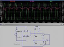
Pictured below is a screen shot of the sim I ran to investigate this.
It is basically a unregulated power supply connected to a class B power output stage to load the rails.
The green trace is the positive rail load current (at 20Hz) and the purple trace is the positive rail voltage.
The red trace is the filtered rail (15ohm / 100uF ~100Hz). As can been seen, 15A peak is not enough current to discharge 20mF fast enough to cause an issue with tracking.
Cheers,
Glen
Attachments

syn08 said:
Why not using this: http://focus.ti.com/lit/ds/symlink/mpy634.pdf It's excellent up to 500-600KHz.
Save some effort to find high precision components (in particular caps) and use this:
http://focus.ti.com/lit/ds/symlink/uaf42.pdf
Free samples available from TI. I used both to build a SVO three years ago, and got excellent results up to 500KHz.
I know that BB part, I think it has been around for longer than me. Can't match the LM4562 for distortion and noise.
Cheers,
Glen
G.Kleinschmidt said:
I know that BB part, I think it has been around for longer than me. Can't match the LM4562 for distortion and noise.
Of course. Good luck sorting and matching caps 😀
BTW, the opamps inside UAF42 are OPA604 (know this from an insider).
cbdb said:
Thanks for the reply. Wow thats a lot of open loop gain! Looks similar to my 2 pole plots. One more question: Dont you measure the phase margin as the minimum margin before the 0db crossing, ie. about 10 degrees? Do lower freq square waves ring? or does the large amount of feedback take care of these prolems? Sorry for all the questions but I have been trying to figure out a way to get rid of this first phase dip; am I wasting my time?
Hi
The phase dip really isn't an issue and will always be there with TPC. NDFL (and TMC, if investigated proerly) actually do the same thing. There isn't any ringing at all on low frequency squarewaves.
There are two things that really matter, as far as stability goes. These are the phase margin at 0dB loop gain and the "gain margin". The latter is the loop gain when the phase shift hits 180 degrees (after the unity loop gain frequency).
In this case the gain marging is 20dB, which is an adequate target.
Cheers,
Glen
syn08 said:
Of course. Good luck sorting and matching caps 😀
BTW, the opamps inside UAF42 are OPA604 (know this from an insider).
There isn't an issue with the caps due to the auto-tune and the UAF42 is also ruled out due to the resistor switching that would be required for range changing. Also think about the resistor values required (and noise) to get down to 20Hz with 1000pF intergrator caps.
Cheers,
Glen
Edmond Stuart said:I don't like that small phase margin either.

You ARE using NDLF again, aren't you?
Re: sudden supply drops
🙁
Not a good tip. The diode will conduct whenever the ripple on the supply rail dips 0.6V below the filtered voltage on the other side of the resistor, pulling the filter cap voltage with it and making the filter quite a waste of time!
For this scheme to work, you need a rather large value resistor, which drops a significant voltage (say, at least 5V under normal operation)
So there goes your headroom!
Cheers,
Glen
Edmond Stuart said:Of course, simply a diode!
Thanks Andy for the tip. 🙂
Cheers.
Edmond.
🙁
Not a good tip. The diode will conduct whenever the ripple on the supply rail dips 0.6V below the filtered voltage on the other side of the resistor, pulling the filter cap voltage with it and making the filter quite a waste of time!
For this scheme to work, you need a rather large value resistor, which drops a significant voltage (say, at least 5V under normal operation)
So there goes your headroom!
Cheers,
Glen
G.Kleinschmidt said:Hi
The phase dip really isn't an issue and will always be there with TPC. NDFL (and TMC, if investigated proerly) actually do the same thing.
NO! NDFL neither TMC does NOT overshoot and the global NFB loop doesn't dip.
There isn't any ringing at all on low frequency squarewaves.
YES, but there is overshoot. Maybe not a problem for you, but I just don't like it.
There are two things that really matter, as far as stability goes. These are the phase margin at 0dB loop gain and the "gain margin". The latter is the loop gain when the phase shift hits 180 degrees (after the unity loop gain frequency).
Yes, as I said already, post #59
In this case the gain marging is 20dB, which is an adequate target.
Yes,
You ARE using NDLF again, aren't you?
Yes! So.....any objections?
BTW, I'm also using ETMC and I have kicked out the CFB-OPS (yes, that's right, one of my own babies!). Far simpler. Distortion is mainly determined by the op-amp in the IPS. With an ideal op-amp THD20=60ppb. How about that? 😀
Not a good tip. The diode will conduct whenever the ripple on the supply rail dips 0.6V below the filtered voltage on the other side of the resistor, pulling the filter cap voltage with it and making the filter quite a waste of time!
For this scheme to work, you need a rather large value resistor, which drops a significant voltage (say, at least 5V under normal operation)
So there goes your headroom!
If 5V, yes, indeed. But why using such a large margin? Doesn't the margin you need depends on the filter time constants and can be kept much smaller?
Anyhow, maybe not such a bright idea. I will think it over.

Cheers,
Glen
Cheers,
Edmond.
Edmond Stuart said:
NO! NDFL neither TMC does NOT overshoot and the global NFB loop doesn't dip.
Who is talking about overshoot? NDFL DOES cause the mid-band phase shift to dip towards 180 degrees just as TPC does. Do a loop gain probe on TMC and similar behaviour can be observed.
Edmond Stuart said:YES, but there is overshoot. Maybe not a problem for you, but I just don't like it.
And I've shown that overshoot about 5 times already. BTW, with a 1MHz ULGF a squarewave input bandwidth limited to greater than 350kHz is required to generate any overshoot.
I don't know of many audio sources that will excite this.
Also, I've decided to live with the overshoot, as a 500-1000 ohm resistor at the amplifiers input (for the low-pass filter) introduces too much hum and distortion.
Edmond Stuart said:
Yes! So.....any objections?
.
Well you say that you "don't like" that TPC causes the mid-band phase to drop towards 180 degrees while ignoring the fact that NDFL does exactly the same thing!!
Edmond Stuart said:
If 5V, yes, indeed. But why using such a large margin? Doesn't the margin you need depends on the filter time constants and can be kept much smaller?
Anyhow, maybe not such a bright idea. I will think it over.
Well how much ripple do you have to reject?
Cheers,
Glen
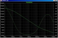
EDIT attached below is the loop gain / phase for my Cherry style NDFL amp, as discussed here:
http://www.diyaudio.com/forums/showthread.php?postid=1770209#post1770209
NDFL doesn't cause the phase to dip??

Attachments
Re: Re: sudden supply drops
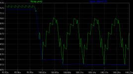
I was looking at something like the pic below. Not sure what you mean about headroom. Sure, it's reduced by the ripple amount, which is what you pay for the ripple not being superimposed on the clipped portion of the waveform with clipped low frequency signals.
G.Kleinschmidt said:For this scheme to work, you need a rather large value resistor, which drops a significant voltage (say, at least 5V under normal operation)
So there goes your headroom!
I was looking at something like the pic below. Not sure what you mean about headroom. Sure, it's reduced by the ripple amount, which is what you pay for the ripple not being superimposed on the clipped portion of the waveform with clipped low frequency signals.
Attachments

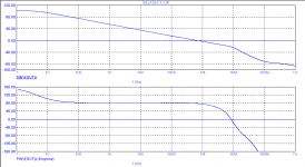
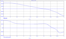
TMC
> Do a loop gain probe on TMC
Yes, Sir! Yes.
Below the global loop response of a blameless amp with TMC.
G.Kleinschmidt said:Who is talking about overshoot? NDFL DOES cause the mid-band phase shift to dip towards 180 degrees just as TPC does. Do a loop gain probe on TMC and similar behaviour can be observed.
[snip]
Well you say that you "don't like" that TPC causes the mid-band phase to drop towards 180 degrees while ignoring the fact that NDFL does exactly the same thing!!
Cheers,
Glen
> Do a loop gain probe on TMC
Yes, Sir! Yes.
Below the global loop response of a blameless amp with TMC.
Attachments
Re: TMC
When did I say "global"?
Edmond Stuart said:
> Do a loop gain probe on TMC
Yes, Sir! Yes.
Below the global loop response of a blameless amp with TMC.
When did I say "global"?
Re: Ndfl+etmc
This is not a phase response of NDFL.
Edmond Stuart said:And here the global loop response of an amp with NDFL+ETMC.
In both cases I got NO overshoot and there is no phase dip around 30kHz or so.
Cheers,
Edmond.
This is not a phase response of NDFL.
Going back to the SVO, has anyone looked at using programmable pots for the resistors in the oscillator? AD do a whole range and there are dual and quad versions.
Same approach for the filters as well.
This might help to avoid lots of relays or complicated switching.
I also saw an article in EDN a while back where they used 8 bit DAC's to do the tuning on an SVF
Same approach for the filters as well.
This might help to avoid lots of relays or complicated switching.
I also saw an article in EDN a while back where they used 8 bit DAC's to do the tuning on an SVF
- Status
- Not open for further replies.
- Home
- Amplifiers
- Solid State
- A superior VAS clamp and VAS current limit for the Blameless.