Yes I also looked for sound at 90 degrees (ie parallel to the speaker) as shown in the zenker plot, and I found nothing. But our equipment is relatively primitive!It's a funny thing about the coincidence frequency. For all of its supposed significance, it's actually pretty hard to detect experimentally (at least for me!).
The early literature suggested exactly what you wrote above: i.e., no significant output below fc. But that is clearly not true, as most DML's operate largely below fc. For example, one of the NXT papers implied that their panels were designed to have fc "outside the audio range" (presumably, above it).
Still, technical papers talk about the large increase in efficiency at fc, along with an increase in off-axis output (at 90 degrees to the panel). But even when I "know" (from calculations) approximately where fc should be, I have never be able to "detect" these features in my own panel measurements. It would seem like fc should show up as a clear spike in the SPL when the mic is positioned at 90 degrees. I've tried many times on many different panels, to find such a spike in the response, but I never saw anything that stuck out as clearly as I had expected. Most recently, I tried with a glass plate, for which the properties are pretty well known, and hence my estimate of fc should have been very reliable. Still, I observed no clear spike in the off axis SPL anywhere near the expected fc.
This image directly below (from a paper by B. Zenker) shows several hemispherical contour plots of different panels, which do show some pretty characteristic features at fc (indicated by the dotted lines). At the indicated fc, the output peaks in intensity at +/-90 degree angles. And above fc, the peak output (in dark red) moves to smaller and smaller angles. A similar characteristic is seen in the plot at the bottom for the Tectonic DML 500, which seems to show the same characteristics starting at about 6kHz.
But with my simple tools (a mic and REW), I have yet to be able to clearly distinguish fc by any direct measurement. If anybody ever finds a simple way to clearly identify fc by direct measurement, I would love to hear about it.
I was really thrilled when I realized that the simple "tap testing"(Christian mentioned in a recent post), revealed so clearly the modal nature of these panel speakers, and allowed the identification of mode shapes, modal frequencies, and even provided a simple way to determine the elastic properties of panels. I felt like my eyes were finally opened to what these panels really do.
But regarding fc, I still feel blind.
Eric
View attachment 1127167
View attachment 1127170
The theory predicts zero far field radiation for an infinite panel, finite panels radiate due to edge and corner modes as we’ve discussed.
DML design seems to be largely about finessing these relatively weak sources of sound. Mode whispering, if you will. ☺️

Mode whispering : nice!Yes I also looked for sound at 90 degrees (ie parallel to the speaker) as shown in the zenker plot, and I found nothing. But our equipment is relatively primitive!
The theory predicts zero far field radiation for an infinite panel, finite panels radiate due to edge and corner modes as we’ve discussed.
DML design seems to be largely about finessing these relatively weak sources of sound. Mode whispering, if you will. ☺️
I can say also I was also not able to find an evidence of the fc as Eric said in the conditions (ie a living room) or tools (mic, REW...) of a DIYer.
Christian
Eric, Christian, Somebody, please.... 🤣I was really thrilled when I realized that the simple "tap testing"(Christian mentioned in a recent post), revealed so clearly the modal nature of these panel speakers, and allowed the identification of mode shapes, modal frequencies, and even provided a simple way to determine the elastic properties of panels. I felt like my eyes were finally opened to what these panels really do.
But regarding fc, I still feel blind.
Eric
Where can I find the original post regarding the Tap Testing technique? I do remember skimming over it about 200 years ago. But it's gone!
Oh! THERE IT IS!!!Eric, Christian, Somebody, please.... 🤣
Where can I find the original post regarding the Tap Testing technique? I do remember skimming over it about 200 years ago. But it's gone!
https://www.diyaudio.com/community/...xcitation-for-dml-design-and-analysis.383567/
Eyes in my *** as usual 🤦♂️. Apologies....
Excellent! Apologies if you've already answered these questions, but I did try to skim all the posts.As requested,
These are designed to be in a closed box or in-wall. I call them hybrid as they operate both as DML and piston. The size is roughly the same as an 15 inch driver ie SD 912 cm2,but the moving mass is only 60g and the BL 29 Tm. Xmax 10mm p-p.
There is a ”regular ” foam surround I made from 1 mm EVA foam. It’s U shaped.
I’m using 6 exciters to drive the panel.
’Frequency range when mounted in-wall is 30-20000 Hz. It’s most likely possible to push them down to 20 with a bit of eq.
measurements from 1m and nearfield few cm.
What are those exciters? (Cant imagine this has not been stated but I didn't find it)
How did you mount the unit in the wall cavity and isolate it from the wall frame? Any photos inside the wall pre-installation?
Im a bit late to this party as I took a breather from the forum (shall we call it counting to ten?).
Perhaps you should look at the in-phase and anti-phase measurements of a pair of DML panels? Second comparison with 1/12 octave smoothingIt's a funny thing about the coincidence frequency. For all of its supposed significance, it's actually pretty hard to detect experimentally (at least for me!).
Attachments

Last edited:
Hello @Alvipet,Perhaps you should look at the in-phase and anti-phase measurements of a pair of DML panels? Second comparison with 1/12 octave smoothing
Glad you are keeping an eye here. Maybe, you can explain those Russian patents better than I try to do. 🙂
By the way, what might be weight of honeycomb panel after the epoxy treatment?
Last edited:
At least Spedge is now part of the carpet crew, what about the rest of you? LOL
That's why I use a ribbon tweeter on my panels, I find it easier to get good low to mid range, material of choice for me is stiff cardboard especially if you are only interested in the low to mid range of a panel, and then let the ribbon do what it is good at for the rest.An excerpt from a Herger Danilo patent of 2021,
View attachment 1125867 View attachment 1125868
The rest you'd have to read with Google translate.
(Well, if someone here says they reached 20k...when the commercially available exciters can hardly reach 10k, no need of further patents. 🙂)
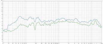
Can you explain this? What is the coincidence freq here (3.5 k?) ? Why does this technique reveal it? Why is one lower SPL? Is the exciter on the mic side or reverse side, and does it matter?Perhaps you should look at the in-phase and anti-phase measurements of a pair of DML panels? Second comparison with 1/12 octave smoothing
Yes, please describe what you did to prepare the stiff cardboard for the panel? And, anything and everything relevant. 🙂...material of choice for me is stiff cardboard especially if you are only interested in the low to mid range of a panel, and then let the ribbon do what it is good at for the rest.
On a DM (distribution mode) panel, there's no pistonic action, even though a pistonic action exciter is used to power it. There's no sound waves running on the surface of panel from the 'exciter' working on it at 90 degrees. It is just the very slight deformations of the panel surface, which are random, the hills and the valleys. The air next to the DM panel moves together with those hiils and valleys, and on both sides of the panel.
The panel is the most important part of the distribution mode, while the 'exciter' is there to transfer the sound energy point-wise from the coil former. The stiffness of the panel, especially the surface, is more important than the flexibility. In a way, the paper cone of the "standard" speaker driver is a DM panel, only just differently shaped.
A force applied at 90 degrees to the panel is actually zero in the panel plane. But, that action derives into ever so slight deformations on the plane of the panel, but are random. Which, in turn gives out the sound, which becomes omnidirectional on the far field (Henry Azima).
Strangely, the rug got more views than the recording!At least Spedge is now part of the carpet crew, what about the rest of you? LOL
Was it the singing?
I have more rugs If anyone is interested 🤣
Steve.
Well, you have already studied them deeply enough). I can give a lost link to the work of the Karavashkins .Glad you are keeping an eye here. Maybe, you can explain those Russian patents better than I try to do. 🙂
By the way, what might be weight of honeycomb panel after the epoxy treatment?
We do not use epoxy resin in our products, so I have no answer to this question.
https://patents.google.com/patent/JP2008109541A/en?oq=JP2008-109541ANo it’s a new innovation😉
The reason for placing them like this is the Piston mode. It was the only way I could think of to achieve symetrical drive of the panel.
Yes there is damping behind the panel and in the wall.Does the box in the wall has the damping material on the back of the box, or just behind the panel? Maybe, because you put the panel in a box, there's good bass output.
Let's try as I understand it: if you carefully read the explanation on Goebel's website at my link, you should have paid attention to the concepts of coincidence frequency - this is the frequency at which the phase velocity of the bending wave becomes equal in value to the phase velocity in air. And thus, from this moment, the piston mode of operation of the membrane begins to appear. Moreover, this process does not occur abruptly, but gradually with a further decrease in frequency. The measurement graph of panels connected out of phase as a whole has a lower sound pressure, which is quite logical due to mutual subtraction. But there is no subtraction at the coincidence frequency point, and therefore the pressure at this point is the same. In this case, it is a point with a value of 1.7 kHz.Can you explain this? What is the coincidence freq here (3.5 k?) ? Why does this technique reveal it? Why is one lower SPL? Is the exciter on the mic side or reverse side, and does it matter?
The exciters on the panels are on the reverse side of the microphone, but in theory this does not matter for the observed effect.
 I’m not sure it’s dealing with the same problem. This patent try to avoid vibration in the panel/diaphragm through using multiple ”exciters”.
I am not.
Anyways, if its an innovation or not is not important for me.
Top is a BMR driver I took apart. Bottom is a exciter. See how thin the voice coil of the BMR is compared to the thick plastic of the exciter.
- Home
- Loudspeakers
- Full Range
- A Study of DMLs as a Full Range Speaker