i made a quick recording of my surround speakers, the sub is set for movies so is a little too loud .
it sounds so good in the kitchen dining room, that i can not help joining in 😀 🙄.
not bad for a very cheep system.
the midrange and above is very nice.
my small panels are far better but would get easily damaged in this position .
it would not be right without the picture of the rug 😎.
steve
it sounds so good in the kitchen dining room, that i can not help joining in 😀 🙄.
not bad for a very cheep system.
the midrange and above is very nice.
my small panels are far better but would get easily damaged in this position .
it would not be right without the picture of the rug 😎.
steve
Attachments
The distance is 120mm.Well, you are going to use them indoors, so the measurements are not the most important matter, but how it sounds to you, and your wife/partner. 🙂
What's interesting is, the transverse waves made by 6 sources at the same time are fighting each other on the same plane and still gives nice output. At what distances, they are placed on the panel? Have you put a rubber puck inside the bobbin/coil-former under the exciter? Do you have the angled lines/cuts on the perimeter of the panel as Gobel's? If so, at what angles, at what distances?
You've left the edges free,
View attachment 1126974 Is it because it acts more like a BMR?
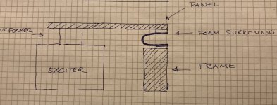
The edges is not free. There is a foam surround so they are in fact closed. Reason being that I wanted an output down to 30 hz.

quick drawing side view.
No there is no puck.

Last edited:
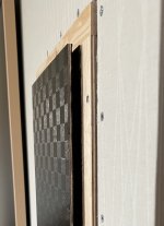
Does the foam surround go right to the end of the panel? In the photo, it looks like the edge is jutting out from the frame (top corner). Isn't the edge of the panel open to the air?The distance is 120mm.
The edges is not free. There is a foam surround so they are in fact closed. Reason being that I wanted an output down to 30 hz. View attachment 1126982
No there is no puck.
EDIT: You've already replied to this question, so disregard the above questions. 🙂
I'll ask some more, though. 🙂 Hope you don't mind.
I have some Sony speakers, I can dismantle them to reclaim the drivers, cut the cones and baskets out to get the motors. The crossovers are there too. Just finished reading the Gobel patent, so the questions. There are few more Russian patents to read too.🙂
Last edited:
Thomas this is very excellent indeed. Well done Sir! Those distortion measurements are amazing!No it’s a new innovation😉
The reason for placing them like this is the Piston mode. It was the only way I could think of to achieve symetrical drive of the panel.
I dont know if there is any penalty in the dml mode? It doesnt seem to, considering the frequency response and distorsion. Maybe some of the wiggles in the frequency respons are due to this. But I wont know before I remove the speakers from the wall and measure them outdoors.
I also suspected that (because of the high driver/panel ratio) your panels can only operate as pistons for the lower part of the spectrum. But this also exposes the surprisingly flat responses of those exciters due to your close-miked measurements. It appears that the "break up"(?) beyond 1.5khz might be due to a combination of acoustic combing as well as panel resonances due to the symmetrical spacing of the drivers.
Are you able to do off-axis measurements to confirm DML action at higher frequencies? Do your panels sound the same whether on-axis or off-axis?
Does the box in the wall has the damping material on the back of the box, or just behind the panel? Maybe, because you put the panel in a box, there's good bass output.The distance is 120mm.
The edges is not free. There is a foam surround so they are in fact closed. Reason being that I wanted an output down to 30 hz.
Hello Thomas,No dsp.
The first two are from 1m . The measurement with a very straight respons is nearfield. you should view them as indicative… I agree that the straight line looks suspicious It’s simply to good…
I will do new measurement, to verify.
Yes, the nearfield measurements are mainly useful up to maybe 1Khz depending of the size of the driver.
The coincidence frequency is around 250 Hz based on the response from the smaller panel which only operates as dml/bending wave. I think the bumps in the response is room influences to some extent And possibly from the fact that they are operating in a ” Box” the wall.
Yes my experience is that it’s really hard to measure omni directional speakers in a room. I prefer to measure them outdoors.
Thomas
Strange value 250Hz for a coincidence frequency. Coincidence frequency is the frequency where the panel wave speed is equal to the sound speed in the air. Usual value are several kHz. Is it what you mean? The product A.f0.fc is constant.
2.A.f0.fc = c² A = 912cm², f0 first mode, fc coincidence frequency, c=344m/s so fc = 250Hz => f0 = 2600Hz... seems too high
Have you evaluated the value of the bending stiffness?
I take the opportunity to reask the model of exciter in the large panel.
Christian
+ @SandasnickarenThanks.
Concerning the goal of stiff and light, I think you are 100% correct, at least with respect to efficiency. And "light" is even more important than "stiff", so yes, minimizing excess epoxy (weight) is a worthy goal. But I don't think it will make the panels sound any better other than to make them louder. So if you are already satisfied with how loud they are, then it may not be worth a great deal of extra effort to further minimize the weight.
3 or even 4 parameters are linked to the bending stiffness and the areal mass : the efficiency, the coincidence frequency, the cut off frequency linked to voice coil mass, the modes linked to the area.
If the efficiency increases as the areal mass decreases, the cut off frequency is also supposed to decrease with decreasing areal mass.
So seems there is a trade off to find between efficiency and bandwidth.
Christian
@Sandasnickaren
How did you arrive at the 6 exciters in the same panel idea? 3 rows and 2 columns idea? And, why?
How did you arrive at the 6 exciters in the same panel idea? 3 rows and 2 columns idea? And, why?
I'm not sure, but did Goebel not mention in his patent something about flexibility in his panel ?
Maybe that is why he used end grain and something to do with the type of resin and cloth ?
I use a little bit of flexibility in my panels, and size matters.
Steve.
Maybe that is why he used end grain and something to do with the type of resin and cloth ?
I use a little bit of flexibility in my panels, and size matters.
Steve.
Here are some options depending which parameters you have on-hand.+ @Sandasnickaren
3 or even 4 parameters are linked to the bending stiffness and the areal mass : the efficiency, the coincidence frequency, the cut off frequency linked to voice coil mass, the modes linked to the area.
If the efficiency increases as the areal mass decreases, the cut off frequency is also supposed to decrease with decreasing areal mass.
So seems there is a trade off to find between efficiency and bandwidth.
Christian
Speed of sound in air, c = 343m/s
ρ = density in kg/m3
L, w, h, are panel dimensions in metres
D = Bending Stiffness in Nm
E = Young's Modulus in Nm
δ = Panel deviation under force in N
Take your pick, good luck! 🙂
Here are some options depending which parameters you have on-hand.
Speed of sound in air, c = 343m/s
ρ = density in kg/m3
L, w, h, are panel dimensions in metres
D = Bending Stiffness in Nm
E = Young's Modulus in Nm
δ = Panel deviation under force in N
Take your pick, good luck! 🙂
View attachment 1127051View attachment 1127052View attachment 1127053
Thanks!Hello Thomas,
Strange value 250Hz for a coincidence frequency. Coincidence frequency is the frequency where the panel wave speed is equal to the sound speed in the air. Usual value are several kHz. Is it what you mean? The product A.f0.fc is constant.
2.A.f0.fc = c² A = 912cm², f0 first mode, fc coincidence frequency, c=344m/s so fc = 250Hz => f0 = 2600Hz... seems too high
Have you evaluated the value of the bending stiffness?
I take the opportunity to reask the model of exciter in the large panel.
Christian
The problem I have is lack value of the bending stiffness and young modulus. Thus not able to calculate.
My assumption was, maybe oversimplified, that the coincidence frequency is 250 Hz, was based on the frequency response on the small panel which only operates as a DML. The response is almost flat down to approx 250 and then it falls like a brick. My understanding of the theory is that there is almost no sound output below the coincidence frequency.
I guess I have to measure the stiffness…still learning😃
Stiffness... You need a kitchen scale and a tape measure....Thanks!
The problem I have is lack value of the bending stiffness and young modulus. Thus not able to calculate.
My assumption was, maybe oversimplified, that the coincidence frequency is 250 Hz, was based on the frequency response on the small panel which only operates as a DML. The response is almost flat down to approx 250 and then it falls like a brick. My understanding of the theory is that there is almost no sound output below the coincidence frequency.
I guess I have to measure the stiffness…still learning😃
The corner you point is linked to the first modes of the plates. Papers give a rule of thumb of a ratio 2.5 between this corner frequency and the first mode below.Thanks!
The problem I have is lack value of the bending stiffness and young modulus. Thus not able to calculate.
My assumption was, maybe oversimplified, that the coincidence frequency is 250 Hz, was based on the frequency response on the small panel which only operates as a DML. The response is almost flat down to approx 250 and then it falls like a brick. My understanding of the theory is that there is almost no sound output below the coincidence frequency.
I guess I have to measure the stiffness…still learning😃
+ @SandasnickarenStiffness... You need a kitchen scale and a tape measure....
Yes it is an option. See here #4185, or #4180 which also gives a formula for predicting the bending stiffness of a sandwich material. An other option is to follow the Tap Test Method proposed by Veleric. To check if some adaptations are needed for composite.
Christian
This is a repeat question,
@Sandasnickaren
How did you arrive at the 6 exciters in the same panel idea? 3 rows and 2 columns idea? And, why?
@Sandasnickaren
How did you arrive at the 6 exciters in the same panel idea? 3 rows and 2 columns idea? And, why?
@Sandasnickaren+ @Sandasnickaren
Yes it is an option. See here #4185, or #4180 which also gives a formula for predicting the bending stiffness of a sandwich material. An other option is to follow the Tap Test Method proposed by Veleric. To check if some adaptations are needed for composite.
Christian
I have a spreadsheet that is based on the equations in post #4180. Using that spreadsheet, I can estimate that the coincidence frequency (fc) of Sandasnickaren's carbon/balsa plate is likely in the neighborhood of 3800 Hz. Note that the bending stiffness estimate that I use neglects shear deformation of the core, and hence may underestimate fc.
And yes, Christian is correct that the tap test method can be used to get a pretty good measure of the panel bending stiffness, and that would be better than the estimate I get from my spreadsheet.
My carbon/balsa plate has a bending stiffness of about 23 Nm. Sandasnickaren's is likely about 15 Nm, due to the thinner carbon layers (about 0.1 mm vs .23 mm and offset slightly by the thicker balsa core (2 mm vs. 1.6 mm). His panel weight is likely about 0.61 Kg/m2.
Using those estimates in this equation (where B is bending stiffness and m' is panel weight per unit area)
gives fc=3775 Hz, give or take....
Eric
There are two speakers, DML or otherwise, placed at least 2 to 3m from each other in most living rooms. So, does anyone listen to them at 1m distance from any given speaker in a standard listening session?
A DML speaker should emit omnidirectional sound in the far-field (Henry Azima), so why measure at 1m, and that too of a single DML panel?
A DML speaker should emit omnidirectional sound in the far-field (Henry Azima), so why measure at 1m, and that too of a single DML panel?
Last edited:
@SandasnickarenThe corner you point is linked to the first modes of the plates. Papers give a rule of thumb of a ratio 2.5 between this corner frequency and the first mode below.
Christian,
True, that corner where the response first peaks is almost certainly related to the lowest modes. For "squarish" plates (aspect ratio under 2.0, say), the second efficient mode (1,3) is usually 2-3 times higher in frequency than the fundamental, hence they are not close enough to avoid leaving a gap in the SPL between them. I think this may be where the 2.5 rule comes from. That is, that the modal density isn't high enough to avoid leaving a gap until you reach the (1.3) mode.
But on my high aspect ratio plates, where the modes are much more closely spaced at the low frequency end, the corner actually corresponds to the fundamental (1,1) rather than the (1,3). I wonder if a similar thing might be true for a sufficiently damped (i.e. amodal bending wave) panel. That is, that the corner might also coincide with the fundamental itself, rather than 2.5 times higher.
Eric
It's a funny thing about the coincidence frequency. For all of its supposed significance, it's actually pretty hard to detect experimentally (at least for me!).My understanding of the theory is that there is almost no sound output below the coincidence frequency.
The early literature suggested exactly what you wrote above: i.e., no significant output below fc. But that is clearly not true, as most DML's operate largely below fc. For example, one of the NXT papers implied that their panels were designed to have fc "outside the audio range" (presumably, above it).
Still, technical papers talk about the large increase in efficiency at fc, along with an increase in off-axis output (at 90 degrees to the panel). But even when I "know" (from calculations) approximately where fc should be, I have never be able to "detect" these features in my own panel measurements. It would seem like fc should show up as a clear spike in the SPL when the mic is positioned at 90 degrees. I've tried many times on many different panels, to find such a spike in the response, but I never saw anything that stuck out as clearly as I had expected. Most recently, I tried with a glass plate, for which the properties are pretty well known, and hence my estimate of fc should have been very reliable. Still, I observed no clear spike in the off axis SPL anywhere near the expected fc.
This image directly below (from a paper by B. Zenker) shows several hemispherical contour plots of different panels, which do show some pretty characteristic features at fc (indicated by the dotted lines). At the indicated fc, the output peaks in intensity at +/-90 degree angles. And above fc, the peak output (in dark red) moves to smaller and smaller angles. A similar characteristic is seen in the plot at the bottom for the Tectonic DML 500, which seems to show the same characteristics starting at about 6kHz.
But with my simple tools (a mic and REW), I have yet to be able to clearly distinguish fc by any direct measurement. If anybody ever finds a simple way to clearly identify fc by direct measurement, I would love to hear about it.
I was really thrilled when I realized that the simple "tap testing"(Christian mentioned in a recent post), revealed so clearly the modal nature of these panel speakers, and allowed the identification of mode shapes, modal frequencies, and even provided a simple way to determine the elastic properties of panels. I felt like my eyes were finally opened to what these panels really do.
But regarding fc, I still feel blind.
Eric
- Home
- Loudspeakers
- Full Range
- A Study of DMLs as a Full Range Speaker

