The pond analogy is, if I understand this correctly, incorrect because it does not include the waves radiating back from the edges of the board that will intersect with the initial waves at different angles thereby chopping the initial wave up into chunks of varying sizes depending on frequency and magnitude. This effectively chops up the phase of the wavefront into pieces.
The best analogy I can think of is when you observe a ‘spiky’ sea where several wave patterns that cross each other at different angles due to reflections from the coast or from changes in weather patterns create a spiky pattern without a discernible wave direction. Little, individual peaks and troughs are generated that jump and and down immediately adjacent to each other in opposite phase.
The other key to understanding, which is beyond my knowledge, lies with the ‘human ears perception or interpretation’ of phase relationships from sound emitted from a source and reflections of that sound.
A bit like the image I posted a couple of pages ago (post #1259). 🙂...
The best analogy I can think of is when you observe a ‘spiky’ sea where several wave patterns that cross each other at different angles due to reflections from the coast or from changes in weather patterns create a spiky pattern without a discernible wave direction. Little, individual peaks and troughs are generated that jump and and down immediately adjacent to each other in opposite phase...
At two different frequencies, the drivers of a speaker can be in phase and out of phase at the same time. It's a contradiction to say a speaker must be either bipole or dipole, and then go on to say that the same speaker is both.
I don't use doublespeak.
Bipole phase cant change as it is always EQUAL. Dipole has degrees of variable phases which mean the phases can change to variable degrees from 1 degree out of phase to 180 degrees out of phase. At 0 degrees it is Bipole because its equal with absolutely no change in phase.
Yeah you guys have it. There are reflections that set up an interference pattern that becomes chaotic.A bit like the image I posted a couple of pages ago (post #1259). 🙂
The analogy of the surface of a body of water that is "choppy" is a good one.
I hosted Mark Fenlon of Mark Audio a few years ago and he described the way his drivers radiated at higher frequencies by pointing to our harbour which that day had a choppy surface. The DML is like that.
I don't think you're correct that bipole phase has to be equal. Around 0 degrees would be fine. It might even be considered bipole from -90 to 90 degree (exclusive). And for dipole you probably meant from 90 to 270 degrees (exclusive). 1 degree out-of-phase would be a bipole for all practical purposes. Not sure why you quoted my post here.
Yeah you guys have it. There are reflections that set up an interference pattern that becomes chaotic.
The analogy of the surface of a body of water that is "choppy" is a good one.
I hosted Mark Fenlon of Mark Audio a few years ago and he described the way his drivers radiated at higher frequencies by pointing to our harbour which that day had a choppy surface. The DML is like that.
So you are comparing a DML to a conventional cone driver like Mark audio? 😀
I don't think you're correct that bipole phase has to be equal. Around 0 degrees would be fine. It might even be considered bipole from -90 to 90 degree (exclusive). And for dipole you probably meant from 90 to 270 degrees (exclusive). 1 degree out-of-phase would be a bipole for all practical purposes. Not sure why you quoted my post here.
You quoted my post so I am responding accordingly. Aight I guess we have to agree to disagree.😎
I forgot that you guys take things so literally... 😉
Why make it simple.eh? ha ha!
Just like in that pond picture, after a while, when the ripples get to the edge of the pond, they bounce back. Same thing happening to the DML panel.
Plus, most of you are using more than one exciter, so the waves will be all over the place.
It seems like chaos, but there is order in that chaos. A computer could actually predict the state of that panel at one given point in time... if it was really chaos, the computer wouldn't be able to make a prediction.
But that was missing the point.
I used that image to see clearly the phase off the surface, instead of a jumble of peaks and dips that would have been harder to relate to.
The point being that over a very short amount of time, phase changes are happening between the front and the back of the panel, changes that we cannot really hear in real time, so it is all "blurred".
That is why there is that diffuse sound in the room, and that is why one can walk around the room, all the way to the edges of the panels and still have the relative same tonal reproduction.
Only in the way the Mark Audio drivers radiate at high frequencies. You need to read more carefully.So you are comparing a DML to a conventional cone driver like Mark audio? 😀
You got it. Now I hope everyone can move on.I forgot that you guys take things so literally... 😉
Why make it simple.eh? ha ha!
Just like in that pond picture, after a while, when the ripples get to the edge of the pond, they bounce back. Same thing happening to the DML panel.
Plus, most of you are using more than one exciter, so the waves will be all over the place.
It seems like chaos, but there is order in that chaos. A computer could actually predict the state of that panel at one given point in time... if it was really chaos, the computer wouldn't be able to make a prediction.
But that was missing the point.
I used that image to see clearly the phase off the surface, instead of a jumble of peaks and dips that would have been harder to relate to.
The point being that over a very short amount of time, phase changes are happening between the front and the back of the panel, changes that we cannot really hear in real time, so it is all "blurred".
That is why there is that diffuse sound in the room, and that is why one can walk around the room, all the way to the edges of the panels and still have the relative same tonal reproduction.
I forgot that you guys take things so literally... 😉
Why make it simple.eh? ha ha!
Just like in that pond picture, after a while, when the ripples get to the edge of the pond, they bounce back. Same thing happening to the DML panel.
Plus, most of you are using more than one exciter, so the waves will be all over the place.
It seems like chaos, but there is order in that chaos. A computer could actually predict the state of that panel at one given point in time... if it was really chaos, the computer wouldn't be able to make a prediction.
But that was missing the point.
I used that image to see clearly the phase off the surface, instead of a jumble of peaks and dips that would have been harder to relate to.
The point being that over a very short amount of time, phase changes are happening between the front and the back of the panel, changes that we cannot really hear in real time, so it is all "blurred".
That is why there is that diffuse sound in the room, and that is why one can walk around the room, all the way to the edges of the panels and still have the relative same tonal reproduction.
I agree they are not chaotic like someone else kept on mentioning. LOL
Now we can move on.
There's a good paper that looks at all this. (one of a few).I forgot that you guys take things so literally... 😉
Why make it simple.eh? ha ha!
Just like in that pond picture, after a while, when the ripples get to the edge of the pond, they bounce back. Same thing happening to the DML panel.
Plus, most of you are using more than one exciter, so the waves will be all over the place.
It seems like chaos, but there is order in that chaos. A computer could actually predict the state of that panel at one given point in time... if it was really chaos, the computer wouldn't be able to make a prediction.
But that was missing the point.
I used that image to see clearly the phase off the surface, instead of a jumble of peaks and dips that would have been harder to relate to.
The point being that over a very short amount of time, phase changes are happening between the front and the back of the panel, changes that we cannot really hear in real time, so it is all "blurred".
That is why there is that diffuse sound in the room, and that is why one can walk around the room, all the way to the edges of the panels and still have the relative same tonal reproduction.
To quote from it...
The waves reflect off edges to
create a semi-random reverberant field. The reverberant field consists of multiple
uncorrelated modes superimposed on one another.
https://web.archive.org/web/2013031...6/files/290707 Final Report - Final Draft.pdf
And to endorse the chaotic point of view...
Jose J. Lopez | Home page
Perhaps I should add that I have experimented with DMLs in some depth and contributed to the original Audio Circle group a few years back. I also have a business relationship with the owner of the rights to the Podium speakers in France.
I've found this discussion here to be a good one with Burntcoils contribution very interesting.
I have loved following this thread and the wonderful contributions from everyone here.
I've looked at both links but the first one is only a webarchive, snapshot of the first page, so no go.
Lopez seems strange to me. He says the panels are excited chaotically, but later on refers to it as an initial impulse followed by distributed modes... which is not chaos!
I think it is just a less than ideal wording when mentioning "chaos" in his paper.
But, let's not get all of us overboard with this.
I'm sure we could find papers online that mention either yes it is chaos, and no it is not.
So, maybe, we can focus on the application more than the theorical views of a subject that doesn't seem to be agreed by everyone.
For us, mere mortals at DIYAudio, just knowing that phase fluctuates and creates this peculiar soundfield should be enough to design panel at home.
I'll let university scientists who have a lot more time discussing and experimenting with it, to come up with a consensus, if they can!
Me, I'll just concentrate on building speakers and listened no to them!
😀
Sorry about the link, it should have been a pdf. It's also found in the references in the Wikipedia entry for DMLs.
Now back to having fun.
Now back to having fun.
Sorry about the link, it should have been a pdf. It's also found in the references in the Wikipedia entry for DMLs.
Now back to having fun.
Wikipedia??? YouTube
After all that bragging about your credentials you need to use the Wikipedia? LMAOROTF
Aight carry on then ol chap.
Ahhh this coffee is so good. My own signature blend with international delight cream and 1 tspn of brown turbanado sugar. LOL
I started building the frames to my tall and narrow panels today but I am taking a coffee break right now. lol
Tip> Panel diaphragm should always be mounted in the middle of the frame. In Jmatts case its ok to mount it in the front because he enclosed the back. But if using as open baffle panel should be mounted in the middle of frame so that every thing is equal.
3mm bamboo ply measurements
These results were from test I did about 4 years ago. Shown is the result for the Dayton Ultra and a Tectonic Exciter that was available from RS Components. It is now obsolete. The panel was 525mm high by 385mm wide and the exciter placed according to standard dml theory ala NXT.
These results were from test I did about 4 years ago. Shown is the result for the Dayton Ultra and a Tectonic Exciter that was available from RS Components. It is now obsolete. The panel was 525mm high by 385mm wide and the exciter placed according to standard dml theory ala NXT.
Attachments
-
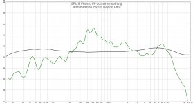 Bamboo Ply Panel Ponoko Cut Dayton Ultra Exciter 1m on axis loosely held vertical.jpg142.7 KB · Views: 468
 -
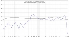 Bamboo Ply Panel Ponoko Cut RS Tectonic Exciter 1m on axis loosely held vertical.jpg143.1 KB · Views: 474
 -
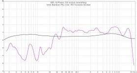 Bamboo Ply Panel Ponoko Cut RS Tectonic Exciter 2.5m on axis loosely held vertical.jpg147.9 KB · Views: 480
Last edited:
Here is the pdf that the link failed to deliver.
That is a very useful paper.
Further thoughts on DML bass.
As Veleric pointed out some posts back a panel of a given ratio and size has a bass reproduction with a specific set of peaks and valleys, DML bass is lumpy because the number of low frequency nodes are limited. One potential solution that I have been exploring is that the panel dimensions can be considered variables that we can use to move the peaks and valleys around in terms of frequency. An appropriate choice of panels with different ratios and therefore different profiles of low frequency peaks and valleys can be used in an array to deliver a flat response.
Damping may have a role in tuning the peak and valleys Q factor, reducing the maximum amplitude of the peaks and valleys and broadening the bandwidth of the peaks and valleys, although this needs to be done with care as damping also effects higher frequencies.
Although multiple panels sounds extravagant it may not necessarily be the case in that the number of additional panels may not be many and there are ways of arranging these panels in an array and within the room that would be domestically acceptable.
There is a further benefit using multiple panels in that for a given volume the multiplicity of exciters employed with an array ( one per panel) would reduce the excursion of the exciters, reducing or eliminating the dreaded exciter rattle without the need for splines.
I will update you all as I go but that might take a while as there are a lot of variables in this approach and they multiply.
Burnt
P.S. I have looked at the literature and cannot find anything on this principle to date, so it may be a unique solution. To all the IP trolls out there, too late, the principle of opperation that would form any patent claim is now in the public domain and free for all to use.
Prior art rocks!
Good thoughts there. I've been wondering about your long narrow panel. It would be interesting to plot its response with a swept tone to see if the bass has lots of peaks and nulls.
- Home
- Loudspeakers
- Full Range
- A Study of DMLs as a Full Range Speaker