The DML driver does not move the whole panel at anything above the second fundamental. It moves a small section just in front of the driver, which then creates a transverse wave moving outwards towards the edge of the panel. Same as a pebble dropped into a pond, the pebble does not move the whole of the content of the pond instantaneously. Therefore one only considers the mass of the panel diaphragm at that frequency which is affected by the driver movement. That specific mass at a specific frequency reduces as the frequency increases.( this situation could be considered as > Mechanical Slew Rate )
When a DML panel is used, the high frequency energy of the exciter finds 'opposing mass' regarding very fast acceleration.
Distortion in DML panels, specifically 3rd harmonic distortion, is generally much lower than in pistonic cones. It's the 3rd harmonic distortion in cones which tells the ear that the speaker is approaching over-drive, and which gives you the impression of how "loud" the speaker is working.So, in practice the high frequency performance of a DML is very much 'a forced thing' > This creates distortion.
This 3rd harmonic distortion is often extremely low in a correctly edge-terminated DML design. One can play the panel very loudly indeed without getting an impression of loudness as-such until you try to speak to the person standing right next to you.
One can play a DML right up to the driver's mechanical limits without any sense of approaching over-drive, and it might appear that the DML over-drives easily. But that's not the case. It's merely a brick-wall limit that allows the panel to play a perfectly clean and crystal clear signal right up to that point where the driver voice-coil hits its mechanical limits.
Last edited:

You can pick up ringing in the spectrogram on REW. It's rare to get resonance or ringing at such high frequencies.Resonance due to ringing especially with polystyrene materials.
Yes, up to 10k or so. They're designed to do that.Dont bells and cymbals ring at high frequencies?
But if your DML panel rings like that then you have a bell or a cymbal, not a loudspeaker. The DML panel should not ring in such a fashion.
In other words, when you strike a cymbal, it carries on producing sound for a long time, many seconds sometimes. If you strike a loudspeaker or a DML panel, it should not not carry on ringing for more than a very small fraction of a second.
Last edited:
Hello Mister Audio,Lets consider music content of 5Khz upwards ...
With a tweeter, the electo-magnetic-motor energy has to only move a diaphragm that has a weight of milligrams.
This allows for fast acceleration and also recovery. It is such characteristics that make tweeters work so well with high frequencies.
( this situation could be considered as > Mechanical Slew Rate )
When a DML panel is used, the high frequency energy of the exciter finds 'opposing mass' regarding very fast acceleration.
So, in practice the high frequency performance of a DML is very much 'a forced thing' > This creates distortion.
Of coarse you don't just add a Tweeter, you also take high frequencies away from the DML panel using a coil/inductor 🙂
Thinking in word of mass in comparison to the standard pistonic model of loudspeaker is probably misleading.
In a DML, the voice coil doesn't push against the mass of the panel but against the combination of the elastic properties of the membrane which is quantified by the mechanical impedance.
It is a bit like an antenna amplifier transmitting the high frequency signal in a coaxial. What is important is the impedance of the cable which the result of the inductance per meter and the capacitance per meter. For sure if there is any parasitic inductance or capacitance at the input, the bandwidth is reduced.
If the shear modulus of the membrane is not high enough, the creation of waves is compromised.
Some phenomena have been already identified here :
- the resonance (modes) of the small disk portion which is clamped at the voice coil edge.
- the noise of the air trying to escape from the volume inside the voice coil below the membrane
There is one mass which is supposed to act as an inductance in a 1st order low pass pass crossover which is the voice coil mass but its effect is here only related to the panel impedance. It is "easier" to get HF from an heavy material (ie acrylic, high mechanical impedance) than from a light one (ie EPS, low mechanical impedance). The mechanical impedance is proportional to the square root of the bending stiffness areal mass product.
The efficiency follows the ratio bending stiffness cube of the areal mass.
So there is trade off bandwitdth/efficiency.
Christian
I won't say the panel below is a good panel but for training and understanding the different phenomena it might be a good one... it is a 30x40cm sheet of 10mm EPS PVA coated only on the exciter side. The resonance of the central area is visible in the 10k area. I modified this area and changed this frequency. I can't recommend the solution I applied as at the end, I created a peak at 6kHz identified by REW as distorsion...You can pick up ringing in the spectrogram on REW. It's rare to get resonance or ringing at such high frequencies.
Due to its early roll off, this panel suffers also probably of a to light material or of a too low shear modulus.
It might be all of that is no more visible on stiffer and or heavier material.
AgreedYes, up to 10k or so. They're designed to do that.
But if your DML panel rings like that then you have a bell or a cymbal, not a loudspeaker. The DML panel should not ring in such a fashion.
In other words, when you strike a cymbal, it carries on producing sound for a long time, many seconds sometimes. If you strike a loudspeaker or a DML panel, it should not not carry on ringing for more than a very small fraction of a second.
It would be interesting to get from psycho-acoustic the order of magnitude of the limit. 50ms? 30ms? as a limit of the hearing integration time?
is looking at the resonances thanks to the spectrogram view a way to select the most appropriate suspension?
Christian
When I'm mixing a vocal track and I want to fatten the voice a bit, then anything more than a 30ms delay over-laid onto the direct voice track becomes identifiable as a separate sound – an echo if you will.It would be interesting to get from psycho-acoustic the order of magnitude of the limit. 50ms? 30ms?
When it's much shorter, and doubled onto the voice it sounds like a chorus;
Shorter than 15ms or so it becomes a flanging effect.
Shorter still and it becomes a phasing effect.
Echo: https://en.wikipedia.org/wiki/Echo
Chorus: https://en.wikipedia.org/wiki/Chorus_(audio_effect)
Flanging: https://en.wikipedia.org/wiki/Flanging
Phasing: https://en.wikipedia.org/wiki/Phaser_(effect)
The flanging/phasing effects were popularised (probably not 'discovered') by the Beatles when they synchronised two tape machines with the identical voice track on both, and then mixed the two identical tracks in through the mixing console. One of the members (anyone of the five, George Martin included) possibly touched the 'flange' of one of the tape reels, and slowed it down a fraction, thereby creating the 'flange' effect where the result was a sweeping comb filter effect as the two tracks went in and out of sync.
https://www.musicradar.com/news/the...g-flanging-debate-has-just-taken-a-weird-turn
Phasing is a bit more subtle, like the rotating horns in the Leslie unit of a Hammond B3 organ. It's not all that easy to imitate the awesomely incredible ear-swooshing effect with digital effects unless you really get into the nitty-gritty of the acoustic physics. But it's a lot of fun to try. It's probably easier and quicker just to BUILD one than to emulate it in the digital realm.
Apologies! Deflections and Rabbit trails...!
But such an interesting subject.
Absolutely - it does.Perhaps it depends on material, coating or exciter used?
With a regular first or second order filter I can definitely hear music content above 4-5Khz.Also, I would say there is no such thing as "musical content above 5k"
I think that is 'playing with words'. A hi hat, for example IS musical content. (and synth goes all the way)
Regarding HIGH FREQUENCY distortion in DML's, the slow slew rate keeps 3rd order harmonic distortion down >Distortion in DML panels, specifically 3rd harmonic distortion, is generally much lower than in pistonic cones. It's the 3rd harmonic distortion in cones which tells the ear that the speaker is approaching over-drive, and which gives you the impression of how "loud" the speaker is working.
however that is actually part of the 'DML High Frequency Sound'.
If you feed a fairly large DML a 5Khz square wave signal, you will actually hear a sound resembling a sign wave.
This also means small, lower mass DML's actually have a more accurate high frequency performance.
I actually corrected that info. to 14/15Khz."singing at 18K"
I CAN DEFINATELY HEAR A BULLET TWEETER "sing at 14/15Khz"
In the end,
I challenge anyone to present an un-doctored plot or example of a DML performing properly at 15Khz !!!
I do hear 15khz just fine and I can definitely tell that HF is missing when I'm A/B listening to my experimental DML panels and my cone-type towers. After a few minutes of DML and I switch back to towers the tower HF seems pretty grating though. I'll be EQ'ing that down on the towers soon... When I EQ a DML to a flatter FR the HF sounds pretty good and I'm looking forward to the day when I'm done experimenting and I have nice DMLs instead of towers 🙂
What does "performing properly" mean? I've got tons of test results but idk if any are worth sharing because idk what you are looking for exactly.
What does "performing properly" mean? I've got tons of test results but idk if any are worth sharing because idk what you are looking for exactly.
Firstly, EQing DML's is definitely the way to go, that's what I did for good sound with mine.
By "performing properly" I mean acoustic output > frequency response.
This 'smoother - less harsh - less grating' sound that people speak of liking is not actually sonic accuracy,
but a function of the physics involved.
If you were to put X value of inductance in series with your Towers, you would say > that's more like my DML's 🙂
Last edited:
Of course you can hear a lot of the frequencies several octaves below cutoff with a first or second order filter.With a regular first or second order filter I can definitely hear music content above 4-5Khz.
I think that is 'playing with words'. A hi hat, for example IS musical content. (and synth goes all the way)
Regarding HIGH FREQUENCY distortion in DML's, the slow slew rate keeps 3rd order harmonic distortion down >
however that is actually part of the 'DML High Frequency Sound'.
If you feed a fairly large DML a 5Khz square wave signal, you will actually hear a sound resembling a sign wave.
This also means small, lower mass DML's actually have a more accurate high frequency performance.
I actually corrected that info. to 14/15Khz.
I CAN DEFINATELY HEAR A BULLET TWEETER "sing at 14/15Khz"
In the end,
I challenge anyone to present an un-doctored plot or example of a DML performing properly at 15Khz !!!
But with a sharp filter at 5K, you will not be able to recognize the track or identify any melodies. Pick any other 2 octaves out with a bandpass and you will actually hear recognizable music instead of occasional pulses of noise. Sure synths and some organs CAN go up over 5k, but that doesn't mean that they do except in some very rare exceptions. Already the top octave on the piano is a relatively recent addition, and didn't exist in the days of Mozart and Beethoven. Some modern composers use it occasionally, but then we are still below 4K.
Obviously you have quite exceptional hearing since you can pinpoint if something sings at either 15 or 18kHz, but for most people a 5KHz square or saw will sound like a sine regardless of the system used.
I'm not saying that you might as well have a low pass on 5k on everything, but it seems very common with people that are not experienced with frequencies and mixing to assign the last couple of octaves more importance than is the case. It is easy to do since numerically it seems like it is 75% of the audible spectrum, but in practice it is a very small slice with about as much musical importance as the band between 20-40Hz. Can add a nice touch when it is there, but contains no fundamental musical information.
In fact a lot of the time as a producer you will routinely both use a HPF and LPF on almost every track because unless it is instruments specifically made to target the lowest and or octaves it will just contain rubbish. It varies a bit between styles, but generally I would say that between 20-120Hz you only allow kick and bass, and above 4K or so you almost only let hi hats and cymbal through.
My point is just that, while I also want a decent response up to at least 15K, it is not an area that is worth too much focus. It seems like HiFi people love to ascribe all sorts of qualities up there. Probably since they cannot really hear it even though it is reproduced, it becomes a good place to stash all sorts of things that is hard to put the finger on.
I asked you to post a graf where the issue you describe is identifiable. I have posted graphs and mdat files you can have a look at. I see no distortion around 15k, do you?
Any standard PC or laptop is going to present ANY signal above 10kHz as a sine wave.I challenge anyone to present an un-doctored plot or example of a DML performing properly at 15Khz !!!
Even if you do manage to feed a perfect square wave directly into your USB converter, by-passing all speakers and microphones, it will still display as a sine wave in your REW oscilloscope. This will be true for all standard set-ups running at 44.1k or 48kHz sampling rate.
If you're lucky enough to be running a system at 96kHz sampling, rate, then you might see what looks like a sine wave with a bit of 2nd harmonic distortion, but still no square wave.
The only way to generate, display and measure square waves above 10Khz is to have:
1. A dedicated external signal generator not feeding its signal through a USB convertor or an audio digital interface of any kind. PC/Laptop audio interfaces are generally limited to audio bandwidths and will sample only-just fast enough to generate or deliver a sine wave at 20kHz without generating Nyquist aliasing artefacts. This means that any signal above 10kHz cannot be analysed for distortion.
2. An external, dedicated distortion analyser that has a bandwidth many times higher than the audio bandwidth depending how many harmonics you want to pick up. a 1MHz bandwidth is probably the minimum you can get away with.
There are wide-band sig gens, distortion analysers and oscilloscopes available that are controlled by standard computers, but which do all of the processing externally to the computer, and then simply feed the results into your PC. These are indispensable when doing real audio work.
I don't know what you mean by "slew rate" wrt a speaker cone or a DML panel.Regarding HIGH FREQUENCY distortion in DML's, the slow slew rate keeps 3rd order harmonic distortion down >
however that is actually part of the 'DML High Frequency Sound'.
Slew rate is used to measure how quickly an amplifier output can change (slew) from max neg to max pos into a load. And the measurement will give you a result in volts-per-microsecond. I've never heard it referring to loudspeakers. Slew rate in v/us cannot be related to loudspeakers.
Is it speaker bandwidth that you're referring to?
Be that as it may, HF distortion might be caused specifically by any exciter with a long-ish voice coil that collapses slightly when driving HF into the panel. But you won't be able to see it, much less measure it with REW (at 48.1kHz sampling rate). And seeing human hearing is limited to 20kHz anyway, there's simply no way anybody is physically able to identify distortion above 10kHz.
3rd harmonic distortion at 10kHz means you're looking at, or hearing, a 30kHz artefact superimposed on the 10kHz signal!
No, it's not the 'slew rate' that keeps the 3rd HD down, it's the whole principle of a DML operation that reduces distortion to very low values—there's no requirement to keep the radiating membrane as a unified plane, vibrating perfectly in phase, as with a speaker cone. THIS is what causes 3rdHD etc in cones and pistons because it's so easy to cause a cone to break-up and distort, and thus deliver signals it was not supposed to generate.
Last edited:
This is no true. The combination of direct sounds + harmonics can still allow track identification to take place.But with a sharp filter at 5K, you will not be able to recognize the track or identify any melodies.
You'd be correct with a highly sharp filter @ 10Khz. That's a whole octave. ( obviously this is music dependent )
This is simply not correct.Obviously you have quite exceptional hearing since you can pinpoint if something sings at either 15 or 18kHz, but for most people a 5KHz square or saw will sound like a sine regardless of the system used.
I was referring to 5Khz not 10, and the 5Khz square wave coming from a signal generator >Any standard PC or laptop is going to present ANY signal above 10kHz as a sine wave.
this being a test scenario to compare the HF performance of a DML compared to a high quality tweeter.
Slew Rate is a term usually used regarding electrical rise time / speed of response. (yes - v/us)Slew rate in v/us cannot be related to loudspeakers.
Is it speaker bandwidth that you're referring to?
It is totally analogous to the speed a speaker can respond to a signal, especially HF impulses.
Bandwidth is actually different, being measured with steady state tones.
However, the shape of a distorted square wave does visually depict bandwidth.
It is this "Speaker Slew Rate" that determines how sinusoidal a 5Khz square wave becomes.
I have never read or heard that the term Slew Rate can't be used in the electro-mechanical domain.
I guess the most common term would be > Transient response.
SO ...3rd harmonic distortion at 10kHz means you're looking at, or hearing, a 30kHz artefact superimposed on the 10kHz signal!
3rd harmonic distortion of 5Khz = 20Khz artifacts.
My point being ... Absolutely NO output @ 20Khz = NO DISTORTION.
Last edited:
@Mister Audio
Since you seem unable to test yourself, I can send you some random but well known tracks with a HPF at 5k. If you can identify one of them I will eat my hat 🤠
And I'm just stating facts. Perhaps you can tell the difference between a 5k square and sine, but very few will be able to. I hear to 16k, but it sounds like a sine to me.
Please before you come with claims like "not true" take the time to verify. Anyone can quite easily verify what I stated for themselves, which makes it a bit silly to argue against it.
Again, where is your analysis showing the issue? And where can you see the issue in my response graphs?
I don't want to argue ...
and I'm not sure that I like the 'tone' of where this is going 😕
I have merely been stating what I know and what I can hear.
and I'm not sure that I like the 'tone' of where this is going 😕
I have merely been stating what I know and what I can hear.
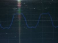
This is not from my signal generator - test equipment.
This is a 5Khz square wave from my laptop line out > through my amp to speaker output >
then back into my laptop through mic input to my PC oscilloscope.
It sure doesn't look like a sine wave to me > contrary to some other comments.
This is a 5Khz square wave from my laptop line out > through my amp to speaker output >
then back into my laptop through mic input to my PC oscilloscope.
It sure doesn't look like a sine wave to me > contrary to some other comments.
Attachments
Sorry, don't want to be harsh or argue, but you did claim that what I said simply was not true, despite it being easily verifiable. So want to be clear that I'm not just making stuff up and encourage people to test for themselves.
I'm not expecting to see a sine from 5KHz. While you need expensive equipment if you want high accuracy in the top frequency bands, most equipment is able to reproduce 20Hz to 20KHz reasonably flat. That is not true for our hearing though. Even if you are a teenager with perfect hearing, the ears sensitivity will quickly slope off above 5kHz (see Fletcher-Munson curve). In the region around 20kHz, where the overtones you are seeing in the waveform would be, your hearing (if perfect) is some 20dB down compared to the 5KHz signal, so about 1% strength compared what you would be seeing on your scope.
I'm not expecting to see a sine from 5KHz. While you need expensive equipment if you want high accuracy in the top frequency bands, most equipment is able to reproduce 20Hz to 20KHz reasonably flat. That is not true for our hearing though. Even if you are a teenager with perfect hearing, the ears sensitivity will quickly slope off above 5kHz (see Fletcher-Munson curve). In the region around 20kHz, where the overtones you are seeing in the waveform would be, your hearing (if perfect) is some 20dB down compared to the 5KHz signal, so about 1% strength compared what you would be seeing on your scope.
Yes - I'm fully aware of the Fletcher Munson curve > but 'loudness buttons' were phased out due to subjectivity.
I think at this point, for everyone's peace of mind, I will respectfully retire from this thread.
Cheers to you all 🙂
I think at this point, for everyone's peace of mind, I will respectfully retire from this thread.
Cheers to you all 🙂
Hi Leob
have you finished building your system? could you tell me
if you have done some tests on how they interact with each other on the same cluster therefore close? if they have the same benefits and above all negative phase interactions as traditional systems
Thank you
have you finished building your system? could you tell me
if you have done some tests on how they interact with each other on the same cluster therefore close? if they have the same benefits and above all negative phase interactions as traditional systems
Thank you
- Home
- Loudspeakers
- Full Range
- A Study of DMLs as a Full Range Speaker