This is sounding promising then...
Offset can drift as the amp warms up so don't get to hung up on that for now. The two presets should not really interact although it may seem that way because both set values drift with temperature.
Any DC offset at the speaker terminals can if a load is connected give an incorrect bias current adjustment... this is why we adjust with no load connected.
So everything seems good with the single pair of output transistors fitted.
What we do now is turn the bias setting back to give zero voltage across the 0.2 ohm (so back to distortion and no current flowing in the output stage) and then we refit the remaining pair of outputs.
Having done that we adjust the bias again, this time following the official procedure and measuring between test points TP2 and TP3.
Look at the circuit.
These test points are across the two 0.05 ohm resistors. The correct setting is to give around 5 millivolts across these two resistors (the resistors appear in series for the measurement, you are measuring across the pair).
So we have I=V/R which is 0.005/(0.05+0.05) which equates to 50 milliamps total current flow or around 17 milliamps per pair of transistors.
Important... the final setting should be done on full mains (no bulb) but we can do this at the very end when (hopefully) it is all fixed.
So having proved it all seems OK you should turn the bias back down zero again... and then work on the other channel.
When we set the bias for the final time we tweak the setting until the amp is fully warmed. Same for the offset. When the amp is warm just set the offset to zero and then forget about it.
This is sounding promising then...
What we do now is turn the bias setting back to give zero voltage across the 0.2 ohm (so back to distortion and no current flowing in the output stage) and then we refit the remaining pair of outputs.
Having done that we adjust the bias again, this time following the official procedure and measuring between test points TP2 and TP3.
These test points are across the two 0.05 ohm resistors. The correct setting is to give around 5 millivolts across these two resistors (the resistors appear in series for the measurement, you are measuring across the pair).
So having proved it all seems OK you should turn the bias back down zero again... and then work on the other channel.
Awesome 🙂
All output transistors fitted. Bias set to 5.2mV. Offset in healthy range.
Result => nice clean audio 🙂
With the left channel now seeming healthy I have set the bias back to zero and disconnected the left board from the amp.
This is great progress 🙂 - now to the right channel...
Has the right channel any obvious issues such as burned parts or failed transistors or are we fault-finding from scratch on this one?
Has the right channel any obvious issues such as burned parts or failed transistors or are we fault-finding from scratch on this one?
No obvious signs of failure - shorts/opens and all the resistors seem Ok
So, proper fault finding then 😉
We link out Q416 and then power it up with the bulb and see what happens.
If the bulb lights we have an output stage problem, if it doesn't light then we see what the DC offset at the output is. If there is a DC offset then the speaker relay should not close and so you need to measure the offset before the relay.
So, proper fault finding then 😉
We link out Q416 and then power it up with the bulb and see what happens.
If the bulb lights we have an output stage problem, if it doesn't light then we see what the DC offset at the output is. If there is a DC offset then the speaker relay should not close and so you need to measure the offset before the relay.
CE of Q314 linked.
Bulb does not light.
Offset at TP5/GND is about 30mV.
Offset at the speaker output is zero. Looks like the signal does not make it to the outputs.
A few things to look at here then.
The offset is good and so if the 30mv on TP5 isn't also appearing at the speaker sockets then it would seem the relay isn't closing for some reason.
It's worth rechecking that result. Make sure the correct sockets are measured and that the speaker switches are in the correct position. Make sure it is not muted.
With no DC offset the speaker protection board and relay driver should operate just the same as it did for the other channel... unless there is some interconnectivity/dependency on needing the other board connected such as power feeds to the protection board etc.
You could try connecting a speaker directly to TP5 but do it via a series resistor of say 100 ohms which will act as a safety net. Use the speaker socket ground for the remaining speaker lead. Remember the volume will be very low with the resistor.
That would prove if audio were present or not.
Also, given the other channel seems OK we could also couple it all up (both channels) and see if that allows the relay to operate normally (assuming we do have a real problem with the relay not operating).
In other words at this stage we might be chasing a problem that isn't real and is caused by not having everything connected.
A few things to look at here then.
It's worth rechecking that result. Make sure the correct sockets are measured and that the speaker switches are in the correct position. Make sure it is not muted.
Rechecked and the offset at TP5 is very erratic. It doesn't creep up slowly and steadily like with the left channel - instead it bounces around constantly. Sometimes it goes between +/- and the reading is all over the place. It starts off jumping between lower values and after a while (5mins) it seems to jump between 34 and 44 mV. So it builds but in a much more erratic fashion than the left channel.
The outputs stay at zero.
With no DC offset the speaker protection board and relay driver should operate just the same as it did for the other channel... unless there is some interconnectivity/dependency on needing the other board connected such as power feeds to the protection board etc.
At least on power up it seems to behave the same with the protection circuit kicking in and the bulb lighting several times before the lights go green and the bulb stays off.
You could try connecting a speaker directly to TP5 but do it via a series resistor of say 100 ohms which will act as a safety net. Use the speaker socket ground for the remaining speaker lead. Remember the volume will be very low with the resistor.
I will try this - just to double check, the one speaker cable should connect to the black socket as normal but the other one should connect to TP5 with the 100 ohm resistor in series?
Also, given the other channel seems OK we could also couple it all up (both channels) and see if that allows the relay to operate normally (assuming we do have a real problem with the relay not operating).
In other words at this stage we might be chasing a problem that isn't real and is caused by not having everything connected.
I fitted the left channel and it made no difference - the left channel continued to see the same offset at TP1 as at the left outputs and the right channel continued to how an erratic offset at TP5 and zero at the right outputs.
The offset should not be erratic and yet in absolute terms the level of offset is pretty low.
It might be worth spending a little time to see why the offset doesn't appear at the speaker socket. If the lights go green it suggests the relay/s should be closed (normal operation) and that must have been the case when the other channel was tested yesterday. So if one channel connects then so should the other as the relay coils are in parallel.
I suspect the diagram has an error in labelling of the relays but it should be easy to check the continuity (check by voltage measurement).
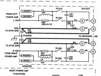
Look at the circuit.
The offset should be present on R20 and R21 on the relay board. One is L channel and one R. See if the erratic offset makes it that far.
If it does then check the appropriate relay has voltage across the coil. If the L channel relay is active then so to the right one should be.
There are two relays per channel, one for speaker set A and the other for speaker set B.
Q725 and Q726 drive the relays. You can see the coils in parallel but the labels don't make sense.... but forget that for now.
When Q725 is on it shows as powering RL01 and RL02 but they don't match what should happen on the relay board where it shows RL01 and RL04 as being left and right.
It should be easy to suss out though. Both speaker sets selected, all the relays should be closed and passing the output to the sockets. So see where the offset goes missing 🙂
It might be worth spending a little time to see why the offset doesn't appear at the speaker socket. If the lights go green it suggests the relay/s should be closed (normal operation) and that must have been the case when the other channel was tested yesterday. So if one channel connects then so should the other as the relay coils are in parallel.
I suspect the diagram has an error in labelling of the relays but it should be easy to check the continuity (check by voltage measurement).
Look at the circuit.
The offset should be present on R20 and R21 on the relay board. One is L channel and one R. See if the erratic offset makes it that far.
If it does then check the appropriate relay has voltage across the coil. If the L channel relay is active then so to the right one should be.
There are two relays per channel, one for speaker set A and the other for speaker set B.
Q725 and Q726 drive the relays. You can see the coils in parallel but the labels don't make sense.... but forget that for now.
When Q725 is on it shows as powering RL01 and RL02 but they don't match what should happen on the relay board where it shows RL01 and RL04 as being left and right.
It should be easy to suss out though. Both speaker sets selected, all the relays should be closed and passing the output to the sockets. So see where the offset goes missing 🙂
The offset should not be erratic and yet in absolute terms the level of offset is pretty low.
It might be worth spending a little time to see why the offset doesn't appear at the speaker socket. If the lights go green it suggests the relay/s should be closed (normal operation) and that must have been the case when the other channel was tested yesterday. So if one channel connects then so should the other as the relay coils are in parallel.
I suspect the diagram has an error in labelling of the relays but it should be easy to check the continuity (check by voltage measurement).
Look at the circuit.
The offset should be present on R20 and R21 on the relay board. One is L channel and one R. See if the erratic offset makes it that far.
If it does then check the appropriate relay has voltage across the coil. If the L channel relay is active then so to the right one should be.
There are two relays per channel, one for speaker set A and the other for speaker set B.
Q725 and Q726 drive the relays. You can see the coils in parallel but the labels don't make sense.... but forget that for now.
When Q725 is on it shows as powering RL01 and RL02 but they don't match what should happen on the relay board where it shows RL01 and RL04 as being left and right.
It should be easy to suss out though. Both speaker sets selected, all the relays should be closed and passing the output to the sockets. So see where the offset goes missing 🙂
Ok, I will investigate this. 😉
Meanwhile I tried what you suggested - connecting the speaker via TP5. It worked and produced clean audio - low in volume as per the 100 ohm resistor. 🙂
Interesting...
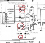
So lets troubleshoot the 'no signal at the output socket' issue. If you study the circuit it should make sense. Each channel output goes through a relay contact. There are two sets of contacts per channel with each corresponding to speaker set A or speaker set B.
So if you turn both speaker sets on then all the relays should be closed. To close the relay the appropriate transistor Q325 or Q326 (or both) needs to be 'on'. Each transistor runs two relays, one left and one right, the other transistor does exactly the same for the second set of speakers.
So if one channel works then the other should as well.
Good to know the audio comes through 🙂
I'll look in later...
Interesting...
So lets troubleshoot the 'no signal at the output socket' issue. If you study the circuit it should make sense. Each channel output goes through a relay contact. There are two sets of contacts per channel with each corresponding to speaker set A or speaker set B.
So if you turn both speaker sets on then all the relays should be closed. To close the relay the appropriate transistor Q325 or Q326 (or both) needs to be 'on'. Each transistor runs two relays, one left and one right, the other transistor does exactly the same for the second set of speakers.
So if one channel works then the other should as well.
Good to know the audio comes through 🙂
I'll look in later...
Checked the resistors leading into the relays. The offset from the right channel is present on R21 so it does make it that far around 30mV.
Across the corresponding coil L2 there is 0.3mV.
I tried the same on the left channel and it looked about the same. The offset from the left was present on R20 and across the coil it was 0.3mV too.
I suppose this points towards the left channel relays themselves?
The offset should appear on the other side of the relay... if one channel works (and we know it does) then the other channel should as well.
The left and right channel relays work together, not independently.
The left and right channel relays work together, not independently.
If RL01 is closed then so to is RL04 (that's one speaker set) and if RL02 is closed then so is RL03
But
those numbers don't agree with the driver circuitry where they show RL01 and RL02 as a pair and RL03 and RL04 as the other pair.
But
those numbers don't agree with the driver circuitry where they show RL01 and RL02 as a pair and RL03 and RL04 as the other pair.
Attachments

The offset should appear on the other side of the relay... if one channel works (and we know it does) then the other channel should as well.
The left and right channel relays work together, not independently.
Yeah, I was looking at the diagram and it looked like RL01/02 are the pair responsible for the left channel terminals and RL03/04 for the right.
But you say that's not correct? In that case i'm very confused 😕
If the signal reaches R21 then there don't appear to be any other components between that point and the speaker terminal - except for the relays and the capacitors C22/24.
It's not worth stressing over trying to figure it out. The bottom line is that with both speaker sets selected (A and B on) all the relays should be powered and passing audio to both sets of sockets.
So whatever offset is appearing at the left of the relay should also appear across those 22nF caps on the other side.
It's worth just rechecking that the audio really is missing from the socket and that it wasn't a measurement anomaly 🙂
So whatever offset is appearing at the left of the relay should also appear across those 22nF caps on the other side.
It's worth just rechecking that the audio really is missing from the socket and that it wasn't a measurement anomaly 🙂
Yeah, I was looking at the diagram and it looked like RL01/02 are the pair responsible for the left channel terminals and RL03/04 for the right.
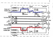
The first diagram shows RL01 and RL02 passing audio to just the left sockets. One is for speaker set A and the other speaker set B
The diagram showing the relay coils shows RL01 and RL02 driven together when they should be driven independently to allow A or B or neither to be on.
For speaker set A to be on you need one upper and one lower relay to be on.
It's not worth stressing over trying to figure it out. The bottom line is that with both speaker sets selected (A and B on) all the relays should be powered and passing audio to both sets of sockets.
So whatever offset is appearing at the left of the relay should also appear across those 22nF caps on the other side.
It's worth just rechecking that the audio really is missing from the socket and that it wasn't a measurement anomaly 🙂
I tried the speaker outputs after hooking into TP5 earlier and the audio was not there. Sadly not an anomaly this time 😉
So I should check the voltage across those caps? They are very difficult to reach from above - should I pop the bottom off and try to probe them from beneath?
It's a very strange issue for sure. It's important the logic of what should happen makes sense in order to troubleshoot it.
The diagram shows left channel in blue and right channel in red. Speaker set A is selected. So RL02A is closed and so is RL03A. So far so good.
Now if we look at the drive to the relays we see that for Speaker A to be on, and Q725 to be on to drive the relay NAD show relay coils RL01 and RL02 as being active. So something is in error in the markings.
So although the error could be anywhere in the markings it's not important because we know that if one channel works the other relay for the other channel should also be powered.
Is it possible that the fault that made it all go 'pop' actually burned a bit of print somewhere (made it go open circuit) or that one of the relay contacts is open circuit?
It will be later today when I look in again 🙂
Try and follow the offset voltage through the relay. If it's not coming out of the relay then check that the relay coil has power across it and also that no print is burned.
Attachments
It will be later today when I look in again 🙂
Try and follow the offset voltage through the relay. If it's not coming out of the relay then check that the relay coil has power across it and also that no print is burned.
It's looking more like one of the relays is the culprit.
I checked all the caps C21/22/23/24.
With only speaker set A selected:
C23 sees the left channel offset
C21 => zero.
C22 => zero.
C24 => zero.
With both speaker set A & B selected:
C23 sees the left channel offset
C21 sees the left channel offset
C22 => zero
C24 => sees the right channle offset.
So it seems that the relays for speaker set B are all OK (RL01/04)
But that only RL02 is OK and RL03 is suspect.
We know that the R21 and the coil L2 must be seeing the correct voltage because speaker set B would need them to work which it does.
Does this sound reasonable?
BTW - please do not feel in any way pressured to respond quickly! Take all the days/weeks you need and only respond when you have nothing better to do 😛 You have a life to live and I realize I am taking up much of your time with this. You are holding my hand through this process in such a way that would be extraordinarily expensive in the "real" world. I can't believe how kind you are to do this. You are a legend

- Home
- Amplifiers
- Solid State
- A sorry tale of woe and stupidity: NAD C370