Make sure the output transistors have been fitted correctly and that any insulation washers are back in place.
What are the insulation washers? The film that is between the heatsink and the transistor or maybe the little round discs that are found on one leg of each of the transistors?
You may need to measure the offset before any speaker relay which may or may not be functional at this point. Measure between ground and the point marked VOP L on the diagram which located at the junction of the 0.05 ohm resistors.
I can use TP4 for ground but can I connect the probe to TP1 to get the point VOP L?
Ok,
I powered her up with just left channel installed.
The bulb lit for a moment then went out and the amp lights turned from green to orange (like when it goes into protection mode) then the bulb lit again for a moment and the lights went from green to orange again - and then finally after the bulb lit once again and went out the amp lights stayed green. Is this because the caps needed to charge up?
After this first time the amp now powers up normally - straight to green and the bulb does not light at all.
I measured between GND/TP1 and the bias slowly rose from 70mV => 85mV where it then seemed to plateau - maxing at 85mV and droppping to 84.5mV every now and again.
I measured at the speaker outputs to and this reading was the same. Seems a bit high.
The insulation washers are indeed the 'film' between the transistors and the heatsink. Old mica washers (clear brittle things) normally have heat sink compound applied to them to help transfer heat, the later silicon rubber types are often used dry.
The collector of 99.9% of devices connects to the metal case or tab of the transistor and so it must be insulated from the heatsink it bolts to. Any bolt/s must also be insulated from that tab although some devices are all plastic where the bolt goes.
Just make sure they are as they originally were.
So... all sounds basically good actually up to this point. The protection circuit behaviour may be unpredictable with only one board powered/fitted so I wouldn't worry to much at this point.
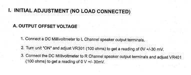
The DC offset should be adjustable as per the manual which is the next thing to try.
The collector of 99.9% of devices connects to the metal case or tab of the transistor and so it must be insulated from the heatsink it bolts to. Any bolt/s must also be insulated from that tab although some devices are all plastic where the bolt goes.
Just make sure they are as they originally were.
So... all sounds basically good actually up to this point. The protection circuit behaviour may be unpredictable with only one board powered/fitted so I wouldn't worry to much at this point.
The DC offset should be adjustable as per the manual which is the next thing to try.
Attachments
Just make sure they are as they originally were.
Check.
So... all sounds basically good actually up to this point. The protection circuit behaviour may be unpredictable with only one board powered/fitted so I wouldn't worry to much at this point.
The DC offset should be adjustable as per the manual which is the next thing to try.
Great stuff. Adjusted the trimmer and now getting 30mV on the output.
That fantastic so far then...
Ideally we want it as close to zero as possible. NAD say within -/+30 millivolts and historically we used to reckon anything under -/+100mv was fine.
So what's next... you could try running audio through this channel. Keep the bulb in place and connect the speaker after having turned the amp on. Keep the volume fairly low.
After that I'd suggest refitting the remaining pair of output transistors, and again we retest checking offset as before although it should be unchanged.
That fantastic so far then...
Ideally we want it as close to zero as possible. NAD say within -/+30 millivolts and historically we used to reckon anything under -/+100mv was fine.
So what's next... you could try running audio through this channel. Keep the bulb in place and connect the speaker after having turned the amp on. Keep the volume fairly low.
After that I'd suggest refitting the remaining pair of output transistors, and again we retest checking offset as before although it should be unchanged.
Brilliant will check that now.
If/When refitting the other output transistors should I also remove the short on Q316?
No, leave Q316 shorted for now.
Will do.
So I ran some audio through and it worked - sort of! 🙂
I just tried some piano at low volume and it came through albeit terribly distorted! I'm guessing the crunchy distortion is expected?
If that's OK I will go ahead refit the remaining output transistors.
How distorted? Did it sound a bit better with the volume up a little?
With no bias (Q316 shorted) you will get crossover distortion but I wouldn't have expected it to be terrible.
With no bias (Q316 shorted) you will get crossover distortion but I wouldn't have expected it to be terrible.
What we could do before refitting the other transistors is to remove the short across Q316.
It is very important (mission critical) that the 500 ohm preset VR302 is first set to its maximum resistance which means it appears as a 500 ohm in circuit.
The amplifier is then tested as before first checking the DC offset.
If that is OK you can carefully adjust VR302 to give around 2.5 millivolts (yes that low) across either of the 0.2 ohms that connect to the pair of transistors you have replaced.
As you turn the preset the bulb may glow dimily as the output stage conducts.
Hopefully the distortion will vanish as you turn the preset.
Be careful measuring, one slip of the probes and it all goes bang. This is all done with no speaker attached.
How distorted? Did it sound a bit better with the volume up a little?
With no bias (Q316 shorted) you will get crossover distortion but I wouldn't have expected it to be terrible.
I didn't up the volume but it was very distorted.
I could tell it was a piano but it sounded like it was going through a guitar fuzz pedal.
What we could do before refitting the other transistors is to remove the short across Q316.
It is very important (mission critical) that the 500 ohm preset VR302 is first set to its maximum resistance which means it appears as a 500 ohm in circuit.
The amplifier is then tested as before first checking the DC offset.
If that is OK you can carefully adjust VR302 to give around 2.5 millivolts (yes that low) across either of the 0.2 ohms that connect to the pair of transistors you have replaced.
As you turn the preset the bulb may glow dimily as the output stage conducts.
Hopefully the distortion will vanish as you turn the preset.
Be careful measuring, one slip of the probes and it all goes bang. This is all done with no speaker attached.
Right, will do this a bit later this evening - have to pop out and run some errands.
Again Mooly - I cannot thank you enough for taking the time to help me. I would be clueless without you. However this all turns out I insist on sending you a bottle of wine or beer or something.
hmm. that's weird - I thought i'd give it a quick try to see if it got better with a bit more volume so I put VR302 back to 158ohms as it was before. I did as before but now there was no sound at all!
Not sure what has happened - VR302 is the only thing that changed and I put it back to the same value.
Oh well, i'm out of time for now. Back later. 😉
Not sure what has happened - VR302 is the only thing that changed and I put it back to the same value.
Oh well, i'm out of time for now. Back later. 😉
Thanks for the kind words, I appreciate it 🙂
Let's get it back to how it was before, even if that means linking out Q316 again. The resistance as measured in circuit of the preset will almost certainly be lower than 500 ohms because of the other bits around it affecting the reading... what we want is it turned fully to the end that gives max resistance (which will be 500 ohms despite what you actually measure). Turn it the other way and it will appear as a zero ohm resistor (a short). That is the way we don't want.
The original setting may give to much or to little bias with the replacement parts fitted, we have no way of knowing without starting from minimum bias and turning it up slowly.
That’s the strange thing - I adjusted VR302 to max resistance intending to remove the short across Q316 but then I decided to first see how the distortion was with a touch more volume so I put VR302 back to how it was around 160 ohms - actually it might have been closer to 150 ohms before any fiddling now I think about it - so perhaps it was up 10 phms more than when there was sound. I did not remove the short at least but could a 10 ohms difference on the trimmer result in no audio at all?
If the short was still in place then the preset adjustment actually has no effect at all. Only with the short removed will the preset do anything.
If you have no audio with the short still in place then it sounds like you have some intermittent connection problem somewhere.
Always fall back to checking basics when something doesn't work as expected. If you have no audio then check the DC offset is still around zero volts and that the supplies are still correct.
(With the short removed, a small difference in setting of the preset can make quite a difference to the current flowing... and this is where the bulb hopefully prevents any disasters should that happen)
If you have no audio with the short still in place then it sounds like you have some intermittent connection problem somewhere.
100% correct again Mooly! 🙂
Turned out to be a loose connection on CZ303. One of the pins labelled SCG on the board had come loose inside the molex connector - too much plugging in and out. The solder joints on the back of the socket were also very loose.
I refitted a new pin and reflowed the solder and audio was back in business!
This time there was noticeably less distortion. I turned up the volume a little and it may have slightly improved. I still couldn't say the distortion was subtle but it was a little less harsh.
Enough for tonight - tomorrow I will max VR302, remove the short and carefully adjust the voltage across those two 0.2 resistors.
Can't thank you enough - will report back on the progress 😉
OK, just take it slowly and be careful measuring.
OK - I tried to do as you explained and it worked - no distortion 🙂
I removed the short then checked the offset again - it was a bit high around 70mV so I trimmed it to 20mV. I left it a good while because I first trimmed it to around 10mV but it slowly crept upwards. I was worried it would continue creeping but eventually it stabilized around 20mV.
Next I measured across the resistors - 0mV with VR302 at max resistance.
I slowly adjusted until I had 2.5mV.
I then rechecked the offset again. It had changed from +20mV => -70mV.
I adjusted to bring it up to around 0mV.
I rechecked the voltage across the resistors again and now it had moved from 2.5mV => 1.9mV
I felt this was a reasonable state to retest with some audio and it seems to be good. No audible distortion - the piano sounded clean! 🙂
Is it expected that you would need to balance the two pots to achieve the right values for offset vs voltage across those resistors? Should I continue to tune it to get closer to 2.5mV with a healthy offset?
- Home
- Amplifiers
- Solid State
- A sorry tale of woe and stupidity: NAD C370