Hi,
Background….
I have owned the NAD C370 for about 18 happy years. The only problem I ever had was with the protection circuit.
This I managed to fix by swapping out the capacitors on the protection board and moving the Zener diode to the other side.
The amp continued to work ever since without problems.
Recently I invested in some new studio gear – audio interface, patch bays etc. After reorganizing the room I hooked up the amp to the system and found that only the left speaker had sound.
I checked the signal coming from the audio interface on both channels – no problem there. I checked the signal being sent from the patch bay – no problem there. I swapped the speaker cables on the back of the amp – the sound now came through the right speaker so the speakers are OK and I concluded that the problem must be the right channel on the amp.
I opened up the amp and had a look around. I noticed that one of the four large capacitors (10 000uf) had a little bulge on the top. To check I switched the left and right pairs over… no change so I guess they were OK.
I swapped the left and right pairs of output relays… no change again so I guess these were OK too.
Next I removed and inspected the right power amp board – I found the two large white resistors on each end had cold/loose solder joints, in one case the track had lifted up from the board. A few more solder joints looked suspect so I reflowed them.
Sadly, still no sound from the right channel.
Then an idea came to me – a really stupid idea! I thought I could isolate if the problem was on the power amp board by swapping the left and right boards. I took out both boards and went to connect the molex leads. All of the interconnects were the same apart from one small lead in the middle. The right side had a connection with 3 pins and the left just two.
Right side…..

Left side….

Without thinking I hooked them up so that all the connectors apart from these two were from the same side – so these ones were crossed over – what a stupid thing to do ☹
I powered on the amp and the green lights flashed on for a moment and then nothing – just a bad smell as something had burnt out. I cursed myself and swapped the boards back. Inspected the fuse and found it was blown.
I replaced the fuse and the amp came on – green lights but now there was no sound from either channel. I noticed that when I touched the two pinned cable on the left board that it made a humming sound.
In despair I looked to Finn.no and found someone was selling a C370 quite close by. I bought it and had it back home the same evening.
I hooked it up to my system and was stunned to find that sound was only in the left speaker!! OMG, this meant that there had been nothing wrong with the amp all along!! Arghhh….
Sure enough the real problem had been with the brand new cable from the patch bay to the amp inputs – can’t believe I did not check that. I checked the cable from audio interface to patch bay and the signal from the patch bay output but missed the cable from the patch bay to the amp – double idiot!
I repaired the cable and sound now came from both speakers.
So, I managed to destroy my perfectly good amp and buy a new identical one when all I needed to do was rewire a cable – I didn’t even think to check it as it was brand new. I could cry.
There is my sorry tale of woe. My question is – do you think there is any way to rescue the old amp? What I did to it is so unusually stupid that I will not find similar accounts or fixes online. Do you have any idea how I could start to find out what damage I did?
I would really appreciate any help anyone could offer on this.
Background….
I have owned the NAD C370 for about 18 happy years. The only problem I ever had was with the protection circuit.
This I managed to fix by swapping out the capacitors on the protection board and moving the Zener diode to the other side.
The amp continued to work ever since without problems.
Recently I invested in some new studio gear – audio interface, patch bays etc. After reorganizing the room I hooked up the amp to the system and found that only the left speaker had sound.
I checked the signal coming from the audio interface on both channels – no problem there. I checked the signal being sent from the patch bay – no problem there. I swapped the speaker cables on the back of the amp – the sound now came through the right speaker so the speakers are OK and I concluded that the problem must be the right channel on the amp.
I opened up the amp and had a look around. I noticed that one of the four large capacitors (10 000uf) had a little bulge on the top. To check I switched the left and right pairs over… no change so I guess they were OK.
I swapped the left and right pairs of output relays… no change again so I guess these were OK too.
Next I removed and inspected the right power amp board – I found the two large white resistors on each end had cold/loose solder joints, in one case the track had lifted up from the board. A few more solder joints looked suspect so I reflowed them.
Sadly, still no sound from the right channel.
Then an idea came to me – a really stupid idea! I thought I could isolate if the problem was on the power amp board by swapping the left and right boards. I took out both boards and went to connect the molex leads. All of the interconnects were the same apart from one small lead in the middle. The right side had a connection with 3 pins and the left just two.
Right side…..
Left side….
Without thinking I hooked them up so that all the connectors apart from these two were from the same side – so these ones were crossed over – what a stupid thing to do ☹
I powered on the amp and the green lights flashed on for a moment and then nothing – just a bad smell as something had burnt out. I cursed myself and swapped the boards back. Inspected the fuse and found it was blown.
I replaced the fuse and the amp came on – green lights but now there was no sound from either channel. I noticed that when I touched the two pinned cable on the left board that it made a humming sound.
In despair I looked to Finn.no and found someone was selling a C370 quite close by. I bought it and had it back home the same evening.
I hooked it up to my system and was stunned to find that sound was only in the left speaker!! OMG, this meant that there had been nothing wrong with the amp all along!! Arghhh….
Sure enough the real problem had been with the brand new cable from the patch bay to the amp inputs – can’t believe I did not check that. I checked the cable from audio interface to patch bay and the signal from the patch bay output but missed the cable from the patch bay to the amp – double idiot!
I repaired the cable and sound now came from both speakers.
So, I managed to destroy my perfectly good amp and buy a new identical one when all I needed to do was rewire a cable – I didn’t even think to check it as it was brand new. I could cry.
There is my sorry tale of woe. My question is – do you think there is any way to rescue the old amp? What I did to it is so unusually stupid that I will not find similar accounts or fixes online. Do you have any idea how I could start to find out what damage I did?
I would really appreciate any help anyone could offer on this.
Attachments
Oh dear 
What's done is done... is it able to be rescued... almost certainly yes by an experienced technician.
It is a case of putting it all back as it should be (all boards and connectors back as original) and then doing basic initial 'cold' tests of all the output stages and low value resistors. That will almost certainly show a problem/s and once 'obvious' damage has been corrected the amp must powered up in a safe and controlled way for further investigation.
Be under no illusions, although it is probably an 'easy' fix it needs a good understanding of circuit theory and interpretation of measurement data. You are probably looking at one or more pairs of output transistors that have failed plus all the collateral damage that follows that failure mode and possibly power supply damage as well due to swapping plugs over.
Thank you Mooly!
That's good to hear and gives me some hope.
By 'cold' you mean without the amp being powered on? If so I could at least attempt this. I can use a multi-meter and despite this solid proof to the contrary - i'm not usually such an idiot. I can probably locate and check the low value resistors but what/where are the output stages?
I suppose this requires a variac?
I see - are the output transistors the line of black rectangular components that are shown below?

Again, many thanks for your wisdom! Much appreciated!
What's done is done... is it able to be rescued... almost certainly yes by an experienced technician.
That's good to hear and gives me some hope.
It is a case of putting it all back as it should be (all boards and connectors back as original) and then doing basic initial 'cold' tests of all the output stages and low value resistors.
By 'cold' you mean without the amp being powered on? If so I could at least attempt this. I can use a multi-meter and despite this solid proof to the contrary - i'm not usually such an idiot. I can probably locate and check the low value resistors but what/where are the output stages?
... the amp must powered up in a safe and controlled way for further investigation.
I suppose this requires a variac?
Be under no illusions, although it is probably an 'easy' fix it needs a good understanding of circuit theory and interpretation of measurement data. You are probably looking at one or more pairs of output transistors that have failed plus all the collateral damage that follows that failure mode and possibly power supply damage as well due to swapping plugs over.
I see - are the output transistors the line of black rectangular components that are shown below?
Again, many thanks for your wisdom! Much appreciated!
Yes, those are the output transistors. Failures will typically read very low ohms or short circuit between collector and emitter. The really low value resistors like the multiple sets of 0.2 and the 0.05 ohm are the first to check.
We normally use a DBT (dim bulb tester) as a limiting device and these can be much better than even a variac.
We normally use a DBT (dim bulb tester) as a limiting device and these can be much better than even a variac.
OK
(In the UK so called 'Pound shops' and cheap hardware stores usually have incandescents)
Ok, I just checked pretty much every component on the left channel power amp board and compared it to the readings from the left channel power amp from the new working device and they are pretty much the same - all resistors and all the output transistors were very close or identical.
OK
(In the UK so called 'Pound shops' and cheap hardware stores usually have incandescents)
Okey doke - The bulbs are on their way so it will be some days before I have the DBT built and ready. By critical voltage readings do you mean checking the rails?
Checking rails (all of them) is always the first thing to check in any faultfinding.
This might give you an idea of how it goes although this is a much more basic design:
Toshiba 330 power amp
Sansui amp keeps blowing fuses after output transistor replacement.
This might give you an idea of how it goes although this is a much more basic design:
Toshiba 330 power amp
Sansui amp keeps blowing fuses after output transistor replacement.
Checking rails (all of them) is always the first thing to check in any faultfinding.
This might give you an idea of how it goes although this is a much more basic design:
Toshiba 330 power amp
Sansui amp keeps blowing fuses after output transistor replacement.
Excellent thank you so much - I will read through these threads and try to glean some information as to how I should proceed.
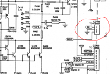
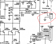
FYI - the fuse only blew the first time after I switched the power amp boards but left the two cables CZ303 amd CZ403 connected and unswitched. After reconnecting the cables correctly the fuse did not blow.
Looking at these cables the right side has 3 pins - 1(BR), 2(GND), 3(BG-D)

whilst the left side has 2 pins - 1(no label) 2(GND).

Any ides what BR and BG-D stand for or what these cables are for?
They go to the switch that allows you to put the amp into bridge ( BR ) mode - so that you can use it as a higher power mono amplifier.
Aha! Thank you
When I swapped the channels over bridge mode was not turned on but it still caused the fuse to pop and enough damage to leave the amp with power but no sound. I wonder what happened..

- Status
- This old topic is closed. If you want to reopen this topic, contact a moderator using the "Report Post" button.
- Home
- Amplifiers
- Solid State
- A sorry tale of woe and stupidity: NAD C370